
Tutorial · Beginner · 20 min read
Build a Line Follower Robot: Sensors to PID Steering
How a line follower robot works: reflectance sensors, a weighted-position error, and a PID loop that steers a differential-drive chassis smoothly.
A line follower is the classic first autonomous robot: it reads a line under its sensors and steers to stay on it. Underneath, it is a small control problem—turn sensor readings into a steering correction—which makes it a perfect way to learn feedback control. Follow along in the Line Follower Simulator.
Sense the line
A reflectance sensor shines infrared light down and measures how much bounces back. A dark line reflects less than the bright surface around it, so each sensor reports whether it is over the line. A bar of several sensors across the front of the robot tells you not just whether you are on the line, but where the line sits relative to center.
Five sensors are a good starting point. Three work at low speed; competition robots often use eight for finer resolution.
Turn readings into one error number
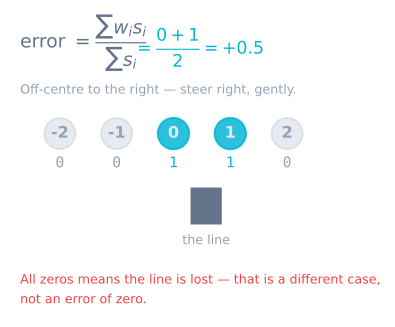
Instead of reacting to individual sensors, combine them into a single weighted position. Give each sensor a position value (negative on the left, zero in the middle, positive on the right) and take the average weighted by how strongly each one sees the line:
// positions: {-2, -1, 0, 1, 2}; readings: reflectance per sensor
float weightedPosition = sum(position[i] * reading[i]) / sum(reading[i]);
The result is your error: zero means centered, negative means the line is to the left, positive to the right. A smooth, continuous error is exactly what a controller needs.
Steer with PID
Feed that error into a PID controller. The correction speeds one wheel and slows the other, turning the robot back toward the line:
float correction = kp * error + ki * integral + kd * derivative;
setMotorSpeeds(baseSpeed - correction, baseSpeed + correction);
Proportional gain drives most of the steering; derivative gain damps the wobble on curves; a small integral term removes any steady drift. If you are new to choosing gains, work through how to tune a PID controller first.
Fix the common failures
- Oscillating around the line: proportional gain is too high or derivative too low. Reduce speed first, then re-tune. On real hardware, a long
delay()in the loop adds dead time that defeats the derivative term. - Losing the line on sharp turns: the robot is outstripping its sensor update rate. Slow down, widen the bar, or reuse the last known line direction so the robot turns back instead of driving straight off.
- Drifting to one side: calibrate the sensors. Sweep them over the line and the background, record each one’s min and max, and normalize live readings against that range.
The whole loop, in one place
The fragments above become a working robot only when the timing, the calibration and the line- loss case are all handled together:
const int N = 5;
const int PIN[N] = {A0, A1, A2, A3, A4};
const int POS[N] = {-2000, -1000, 0, 1000, 2000};   // weights, in the error's units

int minv[N], maxv[N];
long lastError = 0;
float integral = 0;
unsigned long lastMicros = 0;

const float KP = 0.10f, KI = 0.0f, KD = 1.6f;
const int   BASE = 140;                              // out of 255

void loop() {
  // 1. Real elapsed time — never assume the loop period.
  const unsigned long now = micros();
  const float dt = (now - lastMicros) * 1e-6f;
  if (dt < 0.002f) return;                           // cap the rate at 500 Hz
  lastMicros = now;

  // 2. Position from the weighted average.
  long weighted = 0, total = 0;
  for (int i = 0; i < N; i++) {
    const int v = normalized(analogRead(PIN[i]), i);
    if (v > 100) { weighted += (long)v * POS[i]; total += v; }
  }

  // 3. Line lost: hold the last error, do NOT zero it.
  const long error = (total == 0) ? lastError : (weighted / total);

  // 4. PID, with derivative on measurement and conditional integration.
  const float derivative = -(float)(error - lastError) / dt;
  const float candidate = integral + error * dt;
  const float raw = KP * error + KI * candidate + KD * derivative;
  const float correction = constrain(raw, -BASE, BASE);
  if (raw == correction) integral = candidate;

  lastError = error;

  // 5. Differential steering.
  setMotors(BASE - correction, BASE + correction);
}
Five things in there are what separate a robot that follows a line from one that nearly does.
Real dt. Both I and D divide by elapsed time. A loop whose duration changes as you add
features — and it will — computes both against a lie if you assume a constant period.
The v > 100 threshold. Without it, five channels each reading a small floor value drag the
weighted average toward the centre regardless of where the line is. The symptom is a robot that
tracks a bold line well and a faded one badly.
Holding the last error on line loss. Zero means “centred”, so a robot that zeroes drives straight ahead at full speed — away from the line, which was almost certainly curving. Holding the last error keeps it turning the way it was already turning.
Derivative on measurement. Differentiating the error means a setpoint change produces a huge spike. Here the setpoint is always zero so it makes little difference, but the habit is worth forming.
Conditional integration. Once the correction saturates, continuing to accumulate integral just stores up an overshoot to be paid back later.
A tuning order that works
Do not tune all three at once. Set KI = 0 and KD = 0, then:
| Step | Change | Watch for | Stop when |
|---|---|---|---|
| 1 | Raise KP from a small value |
The robot starts responding to the line | It follows a gentle curve, weaving a little |
| 2 | Keep raising KP |
Weaving grows into oscillation | It oscillates steadily — note this value as Ku |
| 3 | Set KP to about half Ku |
Response is quick, overshoot present | — |
| 4 | Raise KD |
The weave damps out | Straights are clean; further KD makes it twitchy |
| 5 | Only if it consistently tracks off-centre, add a little KI |
The offset closes | It closes — KI is rarely needed on a line follower |
| 6 | Raise BASE speed |
Everything degrades together | Re-tune KP and KD at the new speed |
Step 6 is the one people forget: gains are speed-dependent. A tune that is perfect at 140 duty will oscillate at 220, because the same steering correction now produces a bigger change in heading per unit time. Expect to re-tune whenever you change the speed meaningfully.
Integral is genuinely rarely useful here. A line follower’s setpoint is zero and the
disturbances are transient, so there is usually no steady-state offset for KI to close. If you
see a persistent offset, suspect uneven motor trim or an uncalibrated sensor before reaching
for integral gain.
The loop rate quietly caps everything
| Loop rate | Interval | Distance travelled at 0.4 m/s |
|---|---|---|
| 20 Hz | 50 ms | 20 mm between decisions |
| 50 Hz | 20 ms | 8 mm |
| 200 Hz | 5 ms | 2 mm |
| 500 Hz | 2 ms | 0.8 mm |
A robot deciding every 20 mm cannot track a curve tightly no matter how the gains are set, and no derivative term recovers information that was never sampled.
The usual culprits are easy to remove: a delay() anywhere in the loop, Serial.print of more
than a few values at 9600 baud, and reading sensors you do not use. Removing them typically
takes a first build from 50 Hz to several hundred, and the tracking improves without touching
a gain. Measure the rate before you tune, not after.
Troubleshooting
| Symptom | Likely cause | Fix |
|---|---|---|
| Weaves on straights | KP too high or KD too low |
Halve KP, then raise KD |
| Oscillates faster and faster | KP above the ultimate gain |
Reduce until it settles |
| Cuts corners | Too fast for the sensor lead | Slow down, or move the array forward |
| Drives off when it loses the line | Error zeroed on line loss | Hold the last error |
| Tracks well one direction, badly the other | Array not level, or motor trim | Level the array; trim each motor |
| Drifts to one side | Uncalibrated sensors, or motor mismatch | Calibrate per channel, then trim |
| Fine on the bench, wanders on the floor | Ride height changed | 3–8 mm, rigid mount, recalibrate |
| Worked yesterday, sluggish today | Battery voltage | Gains are properties of the plant — re-tune or close a speed loop |
| Jitters at low speed only | Below the motors’ deadband | Measure each motor’s starting duty and compensate |
Nothing responds to KD |
A delay() in the loop |
Dead time defeats derivative action entirely |
Try it yourself
In the Line Follower Simulator you can draw a track, change the sensor count and speed, and tune the gains while watching the error and lap time. Everything you learn about the weighted error and the steering loop carries straight over to an Arduino robot.
Explore the graph
Part of these builds
Projects and learning paths that include this tutorial.
Further reading