
Tutorial · Intermediate · 18 min read
Drive Servos with the PCA9685 (I²C PWM Driver)
How to drive many servos with a PCA9685 over I²C: set the PWM frequency, turn an angle into a calibrated pulse width, and power the servos safely.
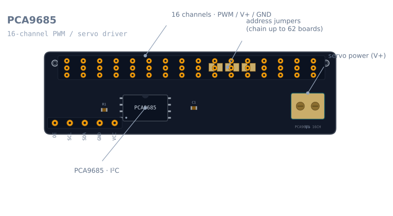
A microcontroller has only a handful of hardware PWM channels. That is fine for one or two servos, but a robot arm has four, a hexapod has eighteen, and the Arduino runs out of timers long before you run out of joints. The PCA9685 solves this: one small board generates sixteen independent PWM signals in hardware, and you command all of them over just two I²C wires. This is how you drive every joint of the robot arm simulator on real hardware.
Why not just wire the servos to the Arduino?
Two reasons. First, pins: the Uno has enough timers for a few Servo objects before the library starts fighting itself. Second, and more important, power: a servo can pull 500–700 mA when it stalls, and four moving at once can pull several amps. That current cannot come from the Arduino’s 5 V pin — it browns out the board and resets it mid-move. The PCA9685 fixes both. It offloads the PWM generation to a dedicated chip, and it routes servo current from its own V+ terminal, keeping the high current away from your logic entirely.
Set the PWM frequency
Every hobby servo expects a 50 Hz control signal — one pulse every 20 ms. The PCA9685 sets one frequency for the whole chip, so you set it once in setup():
#include <Adafruit_PWMServoDriver.h>

Adafruit_PWMServoDriver pwm = Adafruit_PWMServoDriver(0x40);  // default I²C address

void setup() {
  pwm.begin();
  pwm.setPWMFreq(50);   // 50 Hz — the standard servo refresh rate
}
All sixteen channels now pulse at 50 Hz. The angle each servo holds is set by the width of its pulse, not the frequency — that is the part you control per channel.
Angle to pulse width — the calibration that matters
A servo reads the pulse width as a position command: roughly 1 ms for 0°, 1.5 ms for centre, 2 ms for 180°, repeated 50 times a second. This is the same pulse-width-as-angle code the SG90 uses; the PCA9685 just generates it in hardware.
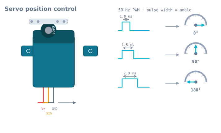
The PCA9685 does not take milliseconds directly. It splits each 20 ms period into 4096 counts (12-bit resolution) and you tell it how many counts the pulse stays high. At 50 Hz, one full period is 4096 counts = 20 ms, so:
- 1 ms ≈ 205 counts (0°)
- 1.5 ms ≈ 307 counts (90°)
- 2 ms ≈ 410 counts (180°)
Those are the nominal numbers. Real servos vary — the same SG90 might bottom out at 130 and top out at 490. This is the one number you must calibrate. Store a min and max per servo and map your angle into that range:
// Calibrate these two per servo by eye — see "Gotchas" below.
const int SERVO_MIN = 130;   // counts at the servo's 0° hard stop
const int SERVO_MAX = 490;   // counts at the servo's 180° hard stop

int angleToCount(int deg) {
  return map(deg, 0, 180, SERVO_MIN, SERVO_MAX);
}
Skipping the calibration is the reason a “90°” command lands at 78° on one joint and 96° on another — and why an arm built on uncalibrated servos never quite reaches the pose the inverse-kinematics solver asked for.
Wiring: two power rails, one ground
- Logic —
VCC,GND,SDA,SCLfrom the Arduino. This powers only the chip. - Servo power — a separate 5–6 V supply to the V+ screw terminal, sized for the stall current of every servo at once, not their idle draw.
- Common ground — the supply’s ground and the Arduino’s ground must be tied together, or the PWM signal has no reference and the servos twitch or ignore you. The same applies to the I²C lines carrying the commands.
Add a capacitor across V+ to absorb the current spike as servos start moving; the PCA9685 breakout has a footprint for exactly this.
The code: move a joint
#include <Adafruit_PWMServoDriver.h>

Adafruit_PWMServoDriver pwm = Adafruit_PWMServoDriver(0x40);

const int SERVO_MIN = 130;
const int SERVO_MAX = 490;

int angleToCount(int deg) {
  return map(deg, 0, 180, SERVO_MIN, SERVO_MAX);
}

void setServo(uint8_t channel, int deg) {
  pwm.setPWM(channel, 0, angleToCount(deg));  // on at count 0, off at the angle count
}

void setup() {
  pwm.begin();
  pwm.setPWMFreq(50);
  setServo(0, 90);   // base to centre
  setServo(1, 45);   // shoulder
  setServo(2, 120);  // elbow
  setServo(3, 10);   // gripper open
}

void loop() {}
Each setPWM(channel, 0, count) says “turn this channel on at the start of the period and off after count ticks.” Sweep a joint by stepping the angle in a loop with a short delay() between steps, so the servo has time to move instead of snapping.
Gotchas
- Calibrate
SERVO_MIN/SERVO_MAXper servo. Command 0°, note where the horn actually sits, and nudge the count until it matches. Do the same at 180°. Ten minutes here saves every downstream pose. - Never drive V+ from the Arduino. One servo might survive it; four will brown out and reset the board.
- Size the supply for stall, not idle. An undersized supply sags when several servos move together, and the whole board jitters.
- Check the address. The default is
0x40. Bridge the solder jumpers to chain boards, and pass the new address to the constructor. - Move gently. Stepping toward a target beats snapping to it — it lowers the current spike and is kinder to plastic gears.
- The gripper channel is the one that cooks. Every other joint reaches its angle and idles; a gripper holding an object is a servo stalled against it, drawing about half an amp continuously. Open it the moment the part is placed, and see servo gripper force, stall and compliance for why finer PWM resolution does not buy you finer force.
Once each joint answers to an angle, the arm is ready for the geometry: turning a target point into the joint angles that reach it, which is exactly what inverse kinematics of a two-link arm and the robot arm simulator are for.
Explore the graph
Part of these builds
Projects and learning paths that include this tutorial.
Further reading