
Tutorial · Intermediate · 35 min
Mecanum Wheel Kinematics: Four Wheels, Three Axes
Derive the four-line inverse kinematics of a mecanum base from one 45° roller, invert it for odometry, and use the spare fourth equation to detect slip.
One roller decides everything
Take one mecanum wheel off the robot and hold it. It spins on its axle like any wheel. Round its rim sit eight or nine barrel-shaped rollers, each on its own little axle, each free to spin, and each set at 45° to the wheel’s axle.
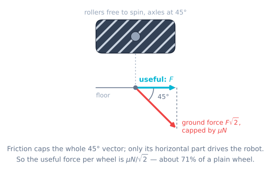
Now ask what force that wheel can put into the floor.
It cannot push along the roller’s rolling direction — the roller just turns and nothing is transmitted. It can only push along the roller’s axle, the one direction the roller refuses to roll in. So the wheel’s ground force is locked to a single line on the floor, at 45° to the chassis, and no amount of motor torque changes which line.
That is the entire mechanism. Everything below is bookkeeping.
The constraint, one wheel at a time
Set up the usual robot frame: x forward, y to the robot’s left, ω counter-clockwise. This is the ROS convention, and using anything else means fighting every library you will ever touch.
Put wheel i at position (xᵢ, yᵢ) in that frame, and give it a roller hand sᵢ = ±1 saying which of the two 45° lines its rollers lie along. Then the wheel’s rim speed vᵢ (in metres per second at the tyre, not radians) relates to the chassis twist by:
vᵢ = vx + sᵢ·vy + (sᵢ·xᵢ − yᵢ)·ωThree terms, and each is worth a sentence:
- vx — every wheel contributes fully to forward motion, whatever its hand. This is why forward on a mecanum base feels completely normal.
- sᵢ·vy — sideways motion drives half the wheels one way and half the other. The hand decides which half.
- (sᵢ·xᵢ − yᵢ)·ω — the moment arm. Note it is not just the track width; the roller hand is inside it, which is why a wheel in the wrong corner ruins rotation as well as strafing.
To go from rim speed to what you actually command a motor, divide by the wheel radius: ωwheel = vᵢ / r, in rad/s.
Four wheels: the matrix
Stack those four rows and you have a 4 × 3 matrix A, with the chassis twist ξ = (vx, vy, ω):
v = A · ξFor the standard layout — front-left and rear-right one hand, front-right and rear-left the other — write k = lx + ly where lx is half the wheelbase (front to rear) and ly is half the track (left to right). Then:
| Wheel | vx | vy | ω |
|---|---|---|---|
| Front left | 1 | −1 | −k |
| Front right | 1 | +1 | +k |
| Rear left | 1 | +1 | −k |
| Rear right | 1 | −1 | +k |
Which is the four lines everybody writes:
float fl = vx - vy - K * omega;
float fr = vx + vy + K * omega;
float rl = vx + vy - K * omega;
float rr = vx - vy + K * omega;
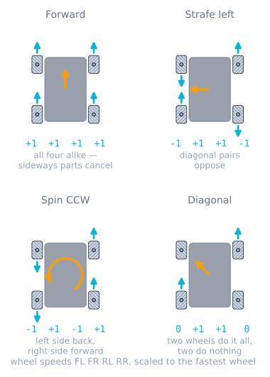
Sanity-check it against the four things you already know a mecanum robot does:
| Command | Wheel speeds (FL, FR, RL, RR) | What you see |
|---|---|---|
| Forward, vx = 1 | 1, 1, 1, 1 | All four the same way. The sideways parts cancel. |
| Strafe left, vy = 1 | −1, 1, 1, −1 | Diagonal pairs oppose. This is the party trick. |
| Spin CCW, ω = 1 | −k, k, −k, k | Left side back, right side forward — an ordinary tank turn. |
| Diagonal, vx = vy = 1 | 0, 2, 2, 0 | Two wheels stop completely. Hold that thought. |
The worked example
A base with lx = 75 mm, ly = 85 mm, 97 mm wheels (r = 48.5 mm), asked for vx = 0.30 m/s, vy = 0.20 m/s, ω = 0.50 rad/s. So k = 0.160 m.
| Wheel | Arithmetic | Rim speed | Motor speed |
|---|---|---|---|
| Front left | 0.30 − 0.20 − 0.160 × 0.50 | 0.020 m/s | 0.41 rad/s (3.9 rpm) |
| Front right | 0.30 + 0.20 + 0.160 × 0.50 | 0.580 m/s | 11.96 rad/s (114 rpm) |
| Rear left | 0.30 + 0.20 − 0.160 × 0.50 | 0.420 m/s | 8.66 rad/s (83 rpm) |
| Rear right | 0.30 − 0.20 + 0.160 × 0.50 | 0.180 m/s | 3.71 rad/s (35 rpm) |
Twenty-nine times the speed on one wheel versus another, from a command that does not look extreme. A mecanum drivetrain spends most of its life with its four motors doing wildly different things, which is why “they all get the same PWM and it drives straight” is not a test that means anything here.
Saturation: scale, never clip
Ask for more than the motors have and you have to give something up. There are exactly two choices and they are not equivalent.
float peak = max(max(fabs(fl), fabs(fr)), max(fabs(rl), fabs(rr)));
if (peak > V_MAX) {            // SCALE: keep the direction, lose the speed
  float s = V_MAX / peak;
  fl *= s; fr *= s; rl *= s; rr *= s;
}
versus the thing that happens if you just write constrain(fl, -255, 255) on each motor: clip. Clipping keeps the speed and throws the direction away. Ask for 0.60 m/s forward, 0.15 sideways and 0.8 rad/s of spin on a robot whose wheels top out at 0.50 m/s:
| Heading | Forward | Spin | Verdict | |
|---|---|---|---|---|
| Commanded | 14.0° | 0.60 m/s | 0.80 rad/s | — |
| Scale | 14.0° | 0.34 m/s | 0.46 rad/s | Slower in every axis, exactly where you pointed |
| Clip | 5.6° | 0.46 m/s | 0.28 rad/s | Faster forward, 8.4° off course, and 40% less spin |
The nastiest part is that clipping looks fine on the commands people test with. A pure diagonal asks two wheels for 2 and two for 0; the zeros are already inside the limit, so clip and scale produce identical numbers and the bug hides. It shows up later, under a path follower, as a robot that leans out of corners for no reason anyone can find. Watch both limiters on the same run and the difference is a curve you can see.
Going backwards: odometry
Forward kinematics is the same matrix read the other way. But A is 4 × 3 — four measurements, three unknowns — so there is no inverse. There is a least-squares solution:
ξ = (Aᵀ A)⁻¹ Aᵀ vFor the standard layout AᵀA comes out diagonal and the whole thing collapses to three lines you can put on an Arduino:
vx    = (fl + fr + rl + rr) / 4.0;
vy    = (-fl + fr + rl - rr) / 4.0;
omega = (-fl + fr - rl + rr) / (4.0 * K);
Integrate that through the robot’s heading each tick and you have dead reckoning:
float dt = (now - last) * 1e-6f;
theta += omega * dt;
x += (vx * cosf(theta) - vy * sinf(theta)) * dt;
y += (vx * sinf(theta) + vy * cosf(theta)) * dt;
Which works exactly as well as the assumption underneath it — that the wheels are not slipping. On a mecanum base, slip is the design point of the wheel, so treat sideways odometry as the least reliable number on the robot.
The fourth equation nobody uses
Four equations, three unknowns. That spare equation is not waste — it is the only free diagnostic on the whole drivetrain.
If the robot is rigid and every wheel is gripping, the four rim speeds cannot be arbitrary. Add the first two rows and the last two rows of the matrix and both come to 2·vx, so:
FL + FR = RL + RRalways, exactly, for any motion a rigid mecanum chassis can perform. So compute the residual every loop:
float residual = (fl + fr) - (rl + rr); // should be ~0 foreverNonzero means the four encoders are describing a motion no solid object can make. Causes, in rough order of likelihood: a wheel off the ground, a wheel on a wet patch, a seized roller, a slipping coupling, a dead encoder channel — or a wheel fitted in the wrong corner, which makes the residual large and constant rather than bursty.
Be honest about what it cannot see: if all four wheels slip the same way at the same time, the residual stays at zero and the robot glides sideways off course in total silence. That blindness is exactly why mecanum odometry fails quietly instead of loudly, and why serious builds add an IMU or unpowered dead wheels rather than trusting the drive encoders.
The two consequences of 45°
Both fall out of the matrix, and neither can be bought off.
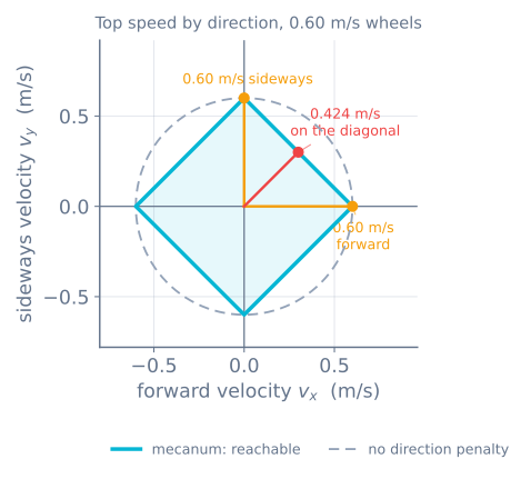
Diagonal motion is limited to 1/√2. A 45° command puts vx + vy on two wheels and 0 on the other two, so the busy pair hits the speed limit when the robot is only moving at V_MAX / √2 ≈ 71% of its straight-line top speed. Faster motors move the ceiling; they do not remove it.
Traction is limited to 1/√2 too, for a different reason. The motor’s useful drive force F sits along the rolling direction, but the actual ground force is F·√2 along the roller axle, and friction caps that. So per wheel the useful force is capped at μN/√2, and the robot’s acceleration ceiling is:
a_max = μ·g / √2On μ = 0.85 that is 5.9 m/s², where the same robot on plain wheels would have 8.3. The robot’s mass cancels out of both, so ballast does not help — a lesson that runs exactly opposite to a sumo robot, where weight is the whole strategy.
In firmware
Put the geometry in one place and never let it be typed twice.
struct Mecanum {
  float lx, ly, r;                 // half wheelbase, half track, wheel radius (m)
  float k() const { return lx + ly; }

  // twist -> four wheel angular velocities, rad/s
  void inverse(float vx, float vy, float w, float out[4]) const {
    out[0] = (vx - vy - k() * w) / r;   // FL
    out[1] = (vx + vy + k() * w) / r;   // FR
    out[2] = (vx + vy - k() * w) / r;   // RL
    out[3] = (vx - vy + k() * w) / r;   // RR
  }

  // four measured wheel angular velocities -> twist, plus the residual
  float forward(const float in[4], float &vx, float &vy, float &w) const {
    float fl = in[0] * r, fr = in[1] * r, rl = in[2] * r, rr = in[3] * r;
    vx = (fl + fr + rl + rr) * 0.25f;
    vy = (-fl + fr + rl - rr) * 0.25f;
    w  = (-fl + fr - rl + rr) * 0.25f / k();
    return (fl + fr) - (rl + rr);       // the free diagnostic
  }
};
Measure lx and ly wheel centre to wheel centre, then halve — not the chassis plate, which is usually wider. Getting k wrong does not stop the robot driving; it makes rotation and translation bleed into each other, so a pure spin command creeps and a pure strafe curves. If your robot creeps while spinning on the spot, suspect k before you suspect the code.
Troubleshooting
| Symptom | Likely cause | What to check |
|---|---|---|
| Forward fine, strafe curves and rotates | A wheel in the wrong corner | The X check from above; the residual will be large and steady |
| Strafes the opposite way to the command | All four wheels mirrored | Swap the left pair with the right pair |
| Spinning on the spot also translates | k wrong, or lx/ly measured on the chassis instead of the wheels | Re-measure wheel centre to wheel centre |
| Diagonal much slower than forward | The 1/√2 ceiling — not a fault | Nothing to fix; design around it |
| Robot leans out of corners under a path follower | Per-motor clipping instead of scaling | Scale the whole command by the worst wheel |
| Odometry drifts fast sideways, fine forward | Roller slip, working as designed | IMU for heading, dead wheels for position |
| Residual spikes on one surface only | That patch is slippery, or a roller is seized | Spin every roller by hand |
Next
Run the numbers against a robot that can slip: the mecanum drive simulator drives these exact equations into a friction model, so you can watch the odometry and the floor disagree. Then make the wheels actually hold the speeds you computed — closed-loop wheel velocity control — and make “forward” mean forward on the floor rather than on the robot with field-oriented drive.
Explore the graph
Part of these builds
Projects and learning paths that include this tutorial.
Further reading