
Tutorial · Beginner · 20 min
Read an IR Reflectance Sensor Array for Line Following
How a line follower turns a row of IR reflectance sensors into one steering error: analog vs digital, calibration, and the weighted-average position formula.
A line-following robot is only as good as the number it steers on. That number comes from a row of infrared reflectance sensors pointed at the floor: the line is one colour, the background another, and the sensors report how much IR light bounces back. This guide turns that raw row of readings into a single, smooth line position—the error your controller acts on.
How a reflectance sensor sees the line
Each sensor pairs an IR LED with a phototransistor. The LED shines down; the phototransistor measures the reflection. A matte black line reflects little IR (low reading); the lighter background reflects more (high reading). Sweep the array across a black-on-white track and each sensor swings between a “on the line” value and an “off the line” value.
Two things change those raw values run to run: sensor height above the surface and ambient light. That is why you never hard-code thresholds—you calibrate. The same sensors pointed down at a ring border rather than a line become an edge detector, where a missed reading costs the robot the match.
Analog vs digital sensors
- Analog sensors give a continuous value (e.g. 0–1023 on an Arduino ADC). You can tell how far the line is from each sensor, which lets you compute a smooth position and steer proportionally.
- Digital sensors report only on/off after an internal threshold. Simpler to wire, but you lose the in-between information, so steering is coarser.
For proportional line following—the kind you tune with a PID controller—use analog readings. This is the approach the line follower simulator models.
Calibrate first
Before a run, sweep every sensor across both the line and the background and record each sensor’s minimum and maximum. Then normalise each live reading into 0–1000 against its own range:
// Per-sensor calibration captured during a sweep.
int minv[N], maxv[N];

int normalized(int raw, int i) {
  long span = maxv[i] - minv[i];
  if (span <= 0) return 0;                       // sensor never saw contrast
  long v = (long)(raw - minv[i]) * 1000 / span;  // 0 (background) … 1000 (line)
  return constrain(v, 0, 1000);
}
Calibrating per sensor cancels out uneven LED brightness and slight height differences across the bar, so one sensor is not quietly biasing the whole estimate.
From readings to one line position
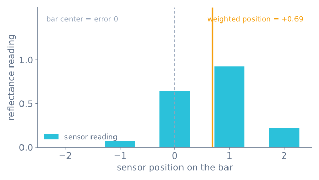
Now collapse the array into a single position with a reflectance-weighted average. Give each sensor a fixed position (…−2, −1, 0, +1, +2… across the bar) and weight it by its normalised reading. The result is the line’s location relative to the bar centre—positive on one side, negative on the other, zero when the line sits dead centre.
// Sensor positions across the bar, e.g. { -2000,-1000,0,1000,2000 }.
long readLinePosition() {
  long weighted = 0, total = 0;
  for (int i = 0; i < N; i++) {
    int v = normalized(analogRead(pins[i]), i);
    weighted += (long)v * position[i];
    total    += v;
  }
  if (total == 0) return lastPosition;  // line lost — reuse last direction
  lastPosition = weighted / total;
  return lastPosition;                  // 0 = centered, sign = which side
}
Two details make this robust:
- Divide by the total reading, not the sensor count, so a faint line and a bold line both map onto the same position scale.
- When every sensor loses the line (
total == 0), reuse the last known position instead of returning zero. That makes the robot keep turning toward where the line was, rather than driving straight off a sharp corner.
How many sensors?
Five is a good starting point—enough to see direction and magnitude while keeping the maths easy to inspect. Three works at low speed; competition robots use eight or more for finer resolution at speed. More sensors mainly buys you a smoother position estimate on tight curves.
The calibration routine, in full
“Calibrate first” is easy to say and easy to do badly. Here is the whole routine, including the guard that stops a dead channel from wrecking the estimate:
const int N = 8;
const int PIN[N] = {A0, A1, A2, A3, A4, A5, A6, A7};
int minv[N], maxv[N];

void calibrate(unsigned long durationMs) {
  for (int i = 0; i < N; i++) { minv[i] = 1023; maxv[i] = 0; }

  const unsigned long start = millis();
  while (millis() - start < durationMs) {
    for (int i = 0; i < N; i++) {
      const int v = analogRead(PIN[i]);
      if (v < minv[i]) minv[i] = v;
      if (v > maxv[i]) maxv[i] = v;
    }
  }

  // A channel that never saw contrast would turn noise into huge normalised
  // values and drag the whole estimate toward itself.
  for (int i = 0; i < N; i++) {
    if (maxv[i] - minv[i] < 50) {
      Serial.print(F("channel dead or never crossed the line: "));
      Serial.println(i);
    }
  }
}
Sweep the array across the line during the whole calibration window. A robot sitting still records the same reading as both its minimum and its maximum, producing a zero span and a sensor that contributes nothing. Rotating the robot in place over the line for three seconds is the standard motion, and it works because every channel crosses the tape.
Recalibrate at the start of every run, not once at build time. Ambient light changes, ride height changes as the battery pack shifts, and the tape picks up dust. This is the single most common reason a line follower works on one table and fails on another.
Killing ambient light
Sunlight contains a great deal of 940 nm infrared, and the phototransistor cannot tell it from your own emitter’s reflection. A robot that works indoors and fails near a window is seeing exactly this.
If your array’s emitters can be switched — most have a LEDON or CTRL pin — the fix is
complete and costs one extra reading per channel:
int ambientSubtracted(int i) {
  digitalWrite(LEDON, LOW);
  delayMicroseconds(200);              // let the phototransistor settle
  const int dark = analogRead(PIN[i]); // ambient only

  digitalWrite(LEDON, HIGH);
  delayMicroseconds(200);
  const int lit = analogRead(PIN[i]);  // ambient + our emitter

  return lit - dark;                   // just our emitter
}
Anything constant in the environment cancels exactly. The cost is double the sampling time, which on a fast line follower is real — but it converts an unreliable sensor into a reliable one, and it is the technique commercial arrays use.
It also has a second benefit worth having: with the emitters off between readings, their average current drops sharply. An 8-channel array’s emitters can draw 100–200 mA continuously, which on a small pack is a meaningful part of the budget.
Losing the line, and finding it again
The total == 0 case above is worth more attention than it usually gets, because it is where
a line follower most often fails visibly.
Returning zero is the obvious implementation and the wrong one: zero means “perfectly centred”, so the robot drives straight ahead at full speed — away from the line it just lost, which was almost certainly curving.
Returning the last position makes the robot keep turning the way it was already turning, which is where the line went. That single change is the difference between a robot that recovers from a sharp corner and one that leaves the track.
A more complete version adds a timeout, so a genuinely lost robot stops rather than spiralling:
long lastPosition = 0;
unsigned long lostSince = 0;

long readLinePosition() {
  long weighted = 0, total = 0;
  for (int i = 0; i < N; i++) {
    const int v = normalized(analogRead(PIN[i]), i);
    if (v > 100) {                    // ignore channels clearly on the floor
      weighted += (long)v * POSITION[i];
      total    += v;
    }
  }

  if (total == 0) {
    if (lostSince == 0) lostSince = millis();
    if (millis() - lostSince > 1500) stopMotors();   // genuinely lost
    return lastPosition;              // keep turning the way we were
  }

  lostSince = 0;
  lastPosition = weighted / total;
  return lastPosition;
}
The v > 100 threshold matters too. Without it, eight channels each reading a small non-zero
floor value pull the weighted average toward the array’s centre regardless of where the line
actually is — which shows up as a robot that tracks well over a bold line and poorly over a
faded one.
Ride height decides the contrast
Reflectance sensors have a narrow sweet spot, and it is the mechanical variable that most often masquerades as a software problem.
| Ride height | What you see in the calibration span |
|---|---|
| 1–3 mm | Largest span, but the array scrapes on any floor irregularity |
| 3–8 mm | The usable band. Most arrays specify around 3 mm |
| 8–15 mm | Span shrinking noticeably; normalisation starts amplifying noise |
| > 15 mm | Effectively blind on most surfaces |
Two consequences follow. Mount it rigidly — an array on a flexible bracket changes height as the robot accelerates, which changes the readings, which the control loop interprets as the line moving. And mount it level, because a tilted array gives each channel a different effective height and therefore a different calibration, which shows up as a robot that tracks well in one direction and poorly in the other.
How many sensors, quantified
| Channels | Position resolution across a 19 mm line | Good for |
|---|---|---|
| 3 | Essentially left / centre / right | Understanding the idea |
| 5 | ~4 discrete regions, smooth between them | A first line follower on a gentle track |
| 8 | ~7 regions | Fast tracks, tight curves, junction detection |
| 12–16 | Fine | Competition robots at speed |
The number that matters more than the count is the array width relative to the line. For plain line following, the array needs to be wide enough that at least one sensor is on the floor at each edge of the line — so roughly twice the tape width.
For line maze junction detection the requirement is stricter: the robot recognises a branch by seeing the outermost sensors go dark while the centre is still on the line, so the array must be at least three times the tape width. An 8-channel array at 8 mm spacing is about 60 mm, which is right for 19 mm tape.
Troubleshooting
| Symptom | Likely cause | Fix |
|---|---|---|
| Works on one surface, fails on another | Stale or missing calibration | Recalibrate at the start of every run |
| One channel drags the estimate | Dead emitter — its span is tiny | Check every channel’s maxv − minv; guard on it |
| Robot drives straight on when it loses the line | Returning 0 on line loss | Return the last position instead |
| Tracks over bold tape, wanders over faded tape | Floor noise entering the average | Add the v > 100 threshold |
| Fails near a window | Ambient infrared | Emitter-off subtraction, or shroud the array |
| Position jumps as the line crosses sensors | Not normalised per channel | Calibrate each channel against its own min and max |
| Readings drift over a long run | Battery sagging, so emitters dim | Check the rail under load |
| All channels read the same | Array too high | 3–8 mm, then recalibrate |
| Tracks well one way, poorly the other | Array not level | Each channel has a different effective height |
Where this goes next
That single position value is the error term. Feed it into a control loop that speeds one wheel and slows the other, and you have a line follower. Learn that loop in Tune a PID controller, then try the whole thing end to end in the line follower simulator.
Explore the graph
Part of these builds
Projects and learning paths that include this tutorial.
Further reading