
Tutorial · Intermediate · 35 min
8051 Timers and Software PWM for Motor Control
The 8051 has no PWM hardware, so you build it from a Timer 0 interrupt. The auto-reload arithmetic, the frequency-resolution trade, and driving an H-bridge.
Introduction
An Arduino sets a motor speed with analogWrite(pin, 180). Behind that single call is a hardware peripheral generating a waveform continuously, for free, while the CPU does something else.
The 8051 has no such peripheral. Nothing on the chip can produce a variable-duty waveform. If you want to run a motor at 70% you have to generate the waveform yourself, from a timer interrupt, and you will pay for it in CPU time. Building that is the single most instructive thing you can do on this chip, because it makes visible exactly what analogWrite() was doing for you.
This assumes you have met the ports already. If PWM itself is new, the PWM and H-bridge tutorial covers why switching a motor on and off quickly is equivalent to varying its voltage.
The timers you have
The classic 8051 has two 16-bit timer/counters, Timer 0 and Timer 1; the AT89S52 adds a third. Each counts machine cycles—twelve oscillator periods each—so at 11.0592 MHz a timer ticks every 1.085 µs.
In practice you get one of them for free. Timer 1 is almost always spoken for by the serial port, which derives its baud rate from Timer 1 overflows. That leaves Timer 0 as your general-purpose timer, and it is the one to build PWM on.
Two registers configure them:
TMODpicks the mode. The low nibble is Timer 0, the high nibble Timer 1.TCONholds the run bits (TR0,TR1) and the overflow flags (TF0,TF1).
Timer 0 has four modes, but only one is right for a periodic tick:
| Mode | TMOD low nibble |
What it does |
|---|---|---|
| 0 | 0x00 |
13-bit count — a compatibility relic |
| 1 | 0x01 |
16-bit count, reload by hand every overflow |
| 2 | 0x02 |
8-bit count with automatic reload |
| 3 | 0x03 |
Splits Timer 0 into two 8-bit timers |
Mode 2 is the one you want. On overflow the hardware copies TH0 back into TL0 by itself, so the period stays exact. Mode 1 makes your interrupt service routine reload the count, and every machine cycle between the overflow and your write is a cycle of drift that accumulates forever.
Setting the tick
In mode 2 the timer counts up from TH0 to 255 and overflows, so the period is the distance it has to travel:
cycles per tick = 256 − TH0
tick period     = (256 − TH0) × 12 / f_osc

TH0 = 156, f_osc = 11.0592 MHz
  cycles = 100
  tick   = 100 × 12 / 11 059 200 = 108.5 µs
Enabling it takes five lines:
#include <reg52.h>

TMOD = (TMOD & 0xF0) | 0x02;   // Timer 0 -> mode 2, leave Timer 1 alone
TH0  = 156;                    // auto-reload value: 100 machine cycles
TL0  = 156;                    // first count starts from the same place
ET0  = 1;                      // enable the Timer 0 interrupt
EA   = 1;                      // global interrupt enable
TR0  = 1;                      // start counting
That TMOD & 0xF0 matters. TMOD is not bit-addressable, so writing TMOD = 0x02 clobbers Timer 1’s mode bits along with it—and if the UART is running, you have just broken your serial output while configuring a motor.
PWM out of a counter
With a periodic interrupt in hand, PWM is bookkeeping. Count ticks up to some period length N, and hold the output high while the count is below the duty value:
#define PWM_LEVELS 20          // ticks per PWM period

sbit ENA = P2^0;               // H-bridge enable — the PWM'd pin

volatile unsigned char tick   = 0;
volatile unsigned char duty_a = 0;    // 0 .. PWM_LEVELS

void timer0_isr(void) interrupt 1 {
    if (++tick >= PWM_LEVELS) tick = 0;
    ENA = (tick < duty_a);     // high for the first duty_a ticks of each period
}
interrupt 1 is Timer 0’s vector (address 0x000B). The overflow flag TF0 is cleared by the hardware as it vectors, so unlike the timer flags you poll by hand, there is nothing to reset.
Setting a speed is now just a variable:
duty_a = 14; // 14/20 = 70% duty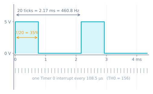
The trade you cannot escape
PWM frequency, duty resolution, and CPU load are one relationship with three names:
f_pwm = f_osc / (12 × C × N)

C = machine cycles per tick  (256 − TH0)
N = ticks per PWM period     (also your number of duty steps)
Hold C at 100 and vary N, and resolution buys itself with frequency:
N |
Duty resolution | PWM frequency | Interrupts/sec |
|---|---|---|---|
| 10 | 10% | 921.6 Hz | 9 216 |
| 20 | 5% | 460.8 Hz | 9 216 |
| 50 | 2% | 184.3 Hz | 9 216 |
| 100 | 1% | 92.2 Hz | 9 216 |
The interrupt rate never changes, because it depends only on C. What changes is how many ticks you spend before the pattern repeats—and below roughly 100 Hz a small DC motor stops averaging the pulses and starts stepping through them audibly.
So take the obvious next step: keep 460.8 Hz and get 1% resolution by setting N = 100 and C = 20. The arithmetic agrees—and the chip dies. At C = 20 the interrupt fires every 20 machine cycles, while the ISR above needs roughly 25 just to save registers, compare, and return. It never finishes before the next one arrives, and nothing else ever executes.
That is the real ceiling. With an ISR costing about 25 machine cycles, C = 100 spends a quarter of the CPU on PWM, and C = 50 spends half. Hardware PWM on an Arduino costs zero, at any frequency and resolution. This one comparison is worth more than any feature table.
Two things buy headroom cheaply: switch to register bank 1 inside the ISR (using 1) so the compiler swaps two bits instead of pushing eight registers, and keep the ISR to counting and pin writes. Anything that computes belongs in main.
Driving the motors
An H-bridge takes two direction inputs and one enable per motor. Feed the direction pins from ordinary port pins and the enable from your PWM’d pin:
sbit IN1 = P2^1;
sbit IN2 = P2^2;
sbit ENA = P2^0;    // PWM'd by the ISR

void motor_forward(unsigned char duty) {
    IN1 = 1; IN2 = 0;
    duty_a = duty;
}

void motor_reverse(unsigned char duty) {
    IN1 = 0; IN2 = 1;
    duty_a = duty;
}

void motor_stop(void) {
    duty_a = 0;
    IN1 = 0; IN2 = 0;
}
A second motor is a second duty variable and a second output line in the same ISR—the tick counter is shared, so both channels stay in step:
void timer0_isr(void) interrupt 1 using 1 {
    if (++tick >= PWM_LEVELS) tick = 0;
    ENA = (tick < duty_a);
    ENB = (tick < duty_b);
}
One wiring detail specific to this chip. As covered in the GPIO tutorial, an 8051 pin sources only tens of microamps. That is plenty for a CMOS input, but an L298N or L293D has bipolar inputs that can draw up to 100 µA at a logic high—right at the edge of what the pin can supply. A 4.7 kΩ pull-up from each driver input to +5 V removes the ambiguity for a few cents, and turns a board that works on the bench but not on the robot into one that just works.
When it goes wrong
- The motor buzzes but barely turns. Your PWM frequency is too low, or the duty is below the motor’s stiction threshold. Raise the frequency above ~100 Hz and expect a real motor to need 25–40% before it moves at all.
- Serial output broke when you added the timer. You wrote
TMODwholesale and cleared Timer 1’s mode bits. Mask it:TMOD = (TMOD & 0xF0) | 0x02;. - The PWM period drifts. You are in mode 1 and reloading by hand. Move to mode 2 and let the hardware do it.
- The whole program crawls. The ISR is too expensive for the tick rate. Raise
TH0toward 200, addusing 1, and move any arithmetic out of the interrupt. - Duty changes glitch the output.
duty_ais being written bymainwhile the ISR reads it. A single-byte write is atomic on this CPU so acharis safe, but anything wider needs the interrupt disabled around the update. - One motor ignores you entirely. Check the enable pin is actually the one the ISR drives, and that the driver’s inputs have their pull-ups.
Explore the graph
Part of these builds
Projects and learning paths that include this tutorial.
Further reading