
Tutorial · Advanced · 2 hours
Cascaded PID Control for a Self-Balancing Robot
Build the two nested PID loops a balancing robot needs: an inner loop holding tilt angle and an outer loop that asks for a lean to control position.
Introduction
You have a trustworthy tilt angle. Now you need to keep the robot standing on it — and then, eventually, make it stay in one place rather than drifting across the room while technically upright.
Those are two different jobs, and the mistake almost everyone makes first is trying to do them with one loop. This tutorial builds them as two, nested, which is how real balancing robots are controlled.
Why one loop cannot work
The thing you want is a robot that stays where you put it. The thing you can command is motor torque. Between them sits an inconvenient fact: the only way to change the robot’s position is to first change its tilt.
Try to control position directly — drive the motors in proportion to position error — and the wheels shoot out from under the centre of mass. The body rotates the opposite way and the robot falls over instantly, having moved in the wrong direction on the way down. This is not a tuning problem; the sign of the initial response is genuinely backwards, a property called non-minimum phase.
The way out is to control the two quantities at different speeds, in a cascade.
The structure
   position error → [ OUTER PID ] → tilt target
                                        ↓
   tilt error     → [ INNER PID ] → motor command → robot
                                        ↑
                                   measured tilt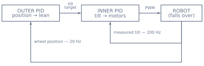
The inner loop does one job: hold whatever tilt angle it is told to. It runs fast — 200 Hz or more — because it is fighting gravity, and gravity does not wait.
The outer loop does the other job: get the robot to a position. It cannot touch the motors, so it works by asking the inner loop for a small lean. Behind where it wants to be, it requests a forward lean; the inner loop drives the wheels to maintain that lean; maintaining a forward lean means continuously accelerating forward. It runs perhaps ten times slower than the inner loop.
That rate separation is the whole design. If the outer loop is anywhere near the speed of the inner loop, they fight — the outer loop changes the target faster than the inner loop can follow it, and the robot oscillates itself into the floor.
The inner loop
float angleError = angle - tiltTarget;      // measured MINUS target
angleIntegral   = constrain(angleIntegral + angleError * dt, -3, 3);

float command = Kp * angleError
              + Ki * angleIntegral
              + Kd * gyroRate;

command = constrain(command, -255, 255);
Three details in there matter more than the gains.
The error is measured minus target, the opposite of the textbook setpoint − measurement. To catch a robot falling forward you drive the wheels forward, under the falling mass, the same way you move your hand under a broom. So a positive tilt must produce a positive motor command. Get this backwards and the controller drives the robot into the floor the instant you switch it on — a distinctive, violent failure that is almost always this sign.
The derivative term uses the gyro rate directly, not a difference of successive angles. The gyroscope measures angular rate as its native output. Differencing a noisy angle signal amplifies exactly the noise you least want amplified, and it is the reason many first attempts need a suspiciously low D gain to stay stable.
The integral is clamped. During a fall the motors saturate and the error keeps growing, so an unclamped integral winds up into a huge number that then fights the recovery on the way back. Clamp it, and stop accumulating entirely while the output is saturated.
The outer loop
if (++slowTick >= 10) {                     // ten times slower
  slowTick = 0;
  float positionError = targetPosition - wheelPosition;
  tiltTarget = constrain(KpPos * positionError - KdPos * wheelVelocity,
                         -0.12, 0.12);      // radians, about ±7°
}
wheelPosition comes from summing your encoder counts. If you have no encoders you can integrate the motor command as a rough proxy, but the loop will be noticeably worse.
The clamp is not optional. An outer loop allowed to demand 30° hands the inner loop a target it physically cannot hold — the robot commits to a lean it cannot recover from and falls while perfectly obeying orders. A few degrees is plenty; a 7° lean accelerates a robot briskly.
Note the velocity term is subtracted. It damps the approach so the robot does not sail past its target and have to come back.
Tuning, in the order that works
Tune the inner loop alone first. Set KpPos and KdPos to zero so the outer loop is inert and tiltTarget stays at zero. The robot will balance in place and slowly drift — that is expected and fine for now.
- Ki and Kd to zero. Raise Kp until the robot reacts sharply to a push. Too low and it sags to the floor without ever really fighting; too high and it buzzes.
- Raise Kd until the oscillation damps out. This is the term that turns a robot which vibrates itself over into one that settles. In the balance simulator you can set D to zero on a running robot and count the swings before it goes down.
- Raise Ki last, and gently. It removes the slow lean caused by IMU mounting trim. Too much and the robot develops a slow, growing wobble as the integral overshoots and unwinds.
Only then enable the outer loop, and start KpPos around a tenth of what feels reasonable. Its effect is indirect — you are watching for the robot to stop drifting, not for a snappy response.
Failure modes and what they mean
| Symptom | Almost always |
|---|---|
| Slams to the floor instantly on power-up | Inner loop sign inverted |
| Oscillates with growing amplitude until it falls | Kd too low, or D taken from differenced angle instead of the gyro |
| Buzzes or vibrates while upright | Kp too high, or loop rate too slow for the gains |
| Balances but slowly drives across the room | IMU mounting trim, with Ki too low to absorb it |
| Balances, then suddenly lurches after a few seconds | Integral wind-up — clamp it |
| Sags gently to the floor without fighting | Kp too low, or motors saturating at their limit |
| Fine alone, wobbles once the outer loop is on | Outer loop too fast or too strong; slow it down and clamp its output harder |
Cut the motors past recovery
if (fabs(angle) > FALL_ANGLE) {             // about 35 degrees
  driveMotors(0, 0);
  angleIntegral = 0;
  return;
}
Past roughly 35° the horizontal acceleration required to get back under the centre of mass exceeds what the wheels can deliver before the body reaches the floor. The controller does not know that and will strain at full torque all the way down, which is hard on gearboxes and makes the failure louder than it needs to be.
Cutting out also resets the integral, so picking the robot back up gives you a clean loop rather than one still carrying a wound-up correction from the fall.
Where to go next
The gains here interact more strongly than in a single-loop PID, because the plant is unstable — there is no “roughly right” that merely performs poorly. It either stands up or it does not.
That makes a simulator unusually useful: you can set D to zero on a robot that is currently balancing, watch the exact failure, and undo it without repairing anything. Try the presets in the balance simulator, then build the real thing in the self-balancing robot project.
Explore the graph
Part of these builds
Projects and learning paths that include this tutorial.
Further reading