
Self-Balancing Robot Simulator: Inverted Pendulum PID
Balance a two-wheeled robot in your browser. Drag it off vertical, shove it, and detune the cascaded PID gains to see exactly how a real balancer falls.
- Category
- Control Systems
- Time
- 2–4 hours
- Platform
- Browser · Arduino
01 / Start here
Introduction
A self-balancing robot is an inverted pendulum: its mass sits above the axle, so standing still is an unstable equilibrium only an active loop can hold. Drag the body over and let go, shove it, or turn the derivative gain to zero and watch the oscillation grow until it hits the floor. The trace plots tilt against the angle past which no motor torque can save it.
Live lab / Inverted pendulum & cascaded PID
Self-balancing robot simulator
A two-wheeled robot with its centre of mass above the axle — an inverted pendulum that falls the moment the loop stops. Drag the body over and let go, shove it, or detune the gains and watch exactly how it fails.
Drag the robot to lean it over and let go — the loop takes it from wherever you leave it. The dashed line is the tilt target the outer loop is asking for; the bar at the axle is the motor command. The trace above plots tilt against the ±35° fall threshold.
- Measured tilt
- Tilt target (outer loop)
- Motor command
- Fall threshold
- Tilt
- 0.0°
- Tilt target
- 0.0°
- Motor
- 0%
- Position
- 0 cm
- Upright for
- 0.0 s
- Worst tilt
- 0.0°
Keyboard: focus the robot, then use Space to run/pause, S to shove it, L to switch the loop on or off, R to reset, and F for full screen.
Controls
Start, Pause and Reset run the loop. Shove delivers an impulse the way a finger would, and Loop on/off disables both controllers so you can see the bare plant fall.
The most direct control is the robot itself: drag the body to any angle and let go. Whatever pose you leave it in is where the controller takes over — there is no re-arm step, and the gain sliders apply to the running simulation immediately. Turn derivative gain to zero while it is balancing and it starts wobbling in that same second.
The Tuning menu loads four presets: one that works, and three that fail in the three ways real balancers fail.
Focus the canvas and use Space, S, L, R and F for the same controls from the keyboard.
Theory
Standing a robot on two wheels means holding an inverted pendulum upright. The centre of mass sits above the axle, so vertical is an equilibrium in the same sense that a pencil balanced on its point is: mathematically real, physically hopeless without constant correction. Tip it by any angle and gravity produces a torque that tips it further. The further it goes, the faster it goes.
The robot has exactly one way to fight that torque — it can move the axle. Accelerating the wheels forward pushes the base back under the centre of mass, which rotates the body back toward vertical. This is why the correction feels inverted at first: to stop falling forward you must drive forward, the same way you move your hand under a broom you are balancing rather than away from it.
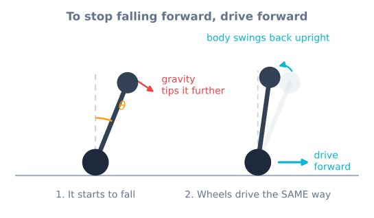
That gives the robot a hard limit. Beyond roughly 35°, the horizontal acceleration needed exceeds what the wheels can deliver before the body hits the floor, and no amount of gain helps. The dashed lines on the trace mark that boundary.
Algorithm
The controller is cascaded — two PID loops, one feeding the other.
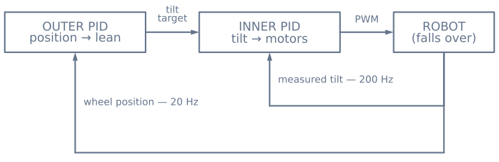
The inner loop runs fast and holds a tilt angle. It compares the measured angle against a target and commands motor torque:
error   = measured_angle − target_angle
motor   = Kp·error + Ki·∫error + Kd·d(measured)/dt
Note the error is measured minus target, not the textbook target minus measured. Catching a forward fall means driving the wheels forward, so a positive tilt has to produce a positive motor command. This sign is the single most common reason a first balancing robot slams itself into the floor the moment it is switched on.
The outer loop runs slower and holds a position. It cannot command the motors — they are already spoken for — so instead it commands a tilt target for the inner loop:
target_angle = Kp_pos·(desired_position − position) − Kd_pos·velocityBehind where it wants to be, it asks for a small forward lean; the inner loop then drives the wheels to hold that lean, and the robot travels forward. The lean is deliberately clamped to a few degrees. An outer loop allowed to demand a large angle will hand the inner loop a target it cannot hold, and both loops lose at once.
The integral term matters more here than in most loops, because it is what absorbs the difference between where the IMU thinks vertical is and where vertical actually is. It is also why the integral has to stop accumulating while the motors are saturated — otherwise it winds up during a fall it has no power to prevent, then fights the recovery.
Source code
// Inner loop: tilt → motors. Runs every 5 ms off a timer, not in loop().
float angleError = angle - tiltTarget;          // measured minus target
angleIntegral   = constrain(angleIntegral + angleError * dt, -3, 3);
float command   = Kp * angleError
                + Ki * angleIntegral
                + Kd * gyroRate;                // rate straight from the gyro

command = constrain(command, -255, 255);
if (fabs(angle) > FALL_ANGLE) command = 0;      // past saving; cut the motors
driveMotors(command, command);

// Outer loop: position → tilt target. Runs ten times slower, and may only
// ever ask for a small lean.
if (++slowTick >= 10) {
  slowTick = 0;
  float positionError = 0 - wheelPosition;
  tiltTarget = constrain(KpPos * positionError - KdPos * wheelVelocity,
                         -0.12, 0.12);          // radians, about ±7°
}
Two details carry over directly from this simulator. Take the derivative term from the gyro rate rather than differencing the angle: the gyro measures that rate directly and without the noise that differentiation amplifies. And cut the motors past the recovery angle rather than letting the controller keep straining — it saves the gearboxes and makes the failure obvious instead of violent.
Hardware
The sensor is an MPU6050, which contains both an accelerometer and a gyroscope, because neither alone is usable. The accelerometer knows where down is but is swamped by the robot’s own movement; the gyroscope tracks rotation cleanly but drifts within seconds. A complementary filter fuses them into an angle that is both stable and quick.
Motors need to be geared low enough for torque and quick enough to catch a fall — N20 gearmotors around 200 RPM are a common choice, driven by a TB6612FNG, whose low dropout matters when the loop is asking for small corrections thousands of times a second.
Build it for real in the self-balancing robot project, or start with the reading tilt tutorial if the IMU is new to you.
Assumptions and hardware differences
The model is a 2D inverted pendulum with a single tilt axis, rigid links, no wheel slip and an IMU that reports the true angle and rate with only the drift and noise you dial in. A real balancing robot feels motor torque that changes with battery voltage, encoder quantization, IMU mounting offset and temperature drift, and it can also fall sideways — a degree of freedom this lab removes entirely. The cascaded PID structure and gyro-rate derivative shown here transfer directly, but mounting trim, filter tuning and the fall-angle cutoff must be re-found on the physical chassis.
Circuit diagram
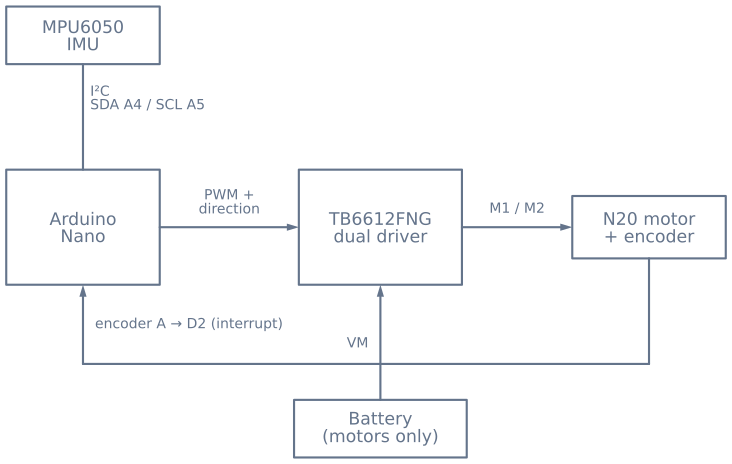
Two wiring rules decide whether this robot works.
The motor battery reaches the driver’s VM pin and nothing else. Motor current must never run through the Arduino, and every ground — board, driver, IMU, battery negative — has to be tied together, or the control signals have no shared reference and the failure is silent rather than obvious.
The encoder is powered from logic, not from the motor rail. Feeding an encoder the motor supply either destroys it or fills the counts with switching noise. Put encoder channel A on an interrupt-capable pin as well; polling it from loop() drops counts, and dropped counts mean the outer loop slowly loses track of where the robot is.
Mount the IMU close to the axle. Mounting it high multiplies the linear acceleration it sees during every correction, which makes the fusion problem harder for no benefit at all.
Hardware checklist
Components
- Arduino Nano or Uno
- MPU6050 accelerometer and gyroscope
- TB6612FNG dual motor driver
- Two N20 encoder gearmotors
- 2S lithium battery pack
Explore the graph
Where this simulator is used
The projects, learning paths, and tutorials that build on this lab.
Continue building
Download resources
Use these on-page references while working through the project. Downloadable project bundles will be added only after their source and version are published.
Common questions
Frequently asked questions
Why does a balancing robot need two PID loops instead of one?
Because the thing you want to control and the thing you can control are different. The motors change wheel speed, but what keeps the robot alive is tilt angle, and the only way to change tilt is to move the wheels underneath the body. So the inner loop holds a tilt angle by driving the motors, and the outer loop asks for a small tilt angle in order to get the robot where you want it. One loop cannot do both: if you drive the motors straight from position error, the robot accelerates out from under its own centre of mass and falls immediately.
Why does my robot slowly drive away even though it looks level?
Almost always mounting trim. If the IMU sits a degree or two off true vertical, the loop faithfully holds that wrong angle, and holding a constant lean means constant acceleration in that direction until you run out of room. Set the trim slider in this lab and you can watch it happen. The fix on real hardware is to measure the offset with the robot held genuinely upright and subtract it, then let the integral term absorb whatever drift is left.
Can I balance without an integral term?
Yes, and the simulator will show you it works — right up until something biases the measurement. P and D alone can hold the robot up, because D supplies the damping that stops the oscillation growing. What they cannot do is remove a steady offset: with any trim error the robot settles at a small permanent lean and creeps away. Integral is what drives that last bit of error to zero.
Why does the robot fall when I set the derivative gain to zero?
Because there is nothing left to damp it. Proportional gain reacts to how far the robot has fallen, but by the time it has corrected, the body is already swinging through vertical with speed. Without a term that responds to how fast the angle is changing, each swing overshoots further than the last until one exceeds the recovery angle. Set D to zero in this lab and you can count the swings.
Why do the wheels drive forward when the robot tips forward?
That is the whole trick, and it is the sign most people get backwards on the first attempt. To stand a broom on your palm you move your hand under the falling end, not away from it. The robot does the same: tilt forward means drive forward to put the wheels back beneath the centre of mass. Reverse that sign and the controller actively shoves the robot down, which looks like an instant, violent fall.
How is this different from the PID controller simulator?
The PID lab controls a stable plant: leave it alone and it simply sits there, so the loop is only improving how quickly and cleanly it reaches a target. This plant is unstable — leave it alone and it falls over, every time. That changes tuning from an optimisation into a requirement, and it is why balancing needs the second, outer loop that the single-loop lab never has to introduce.
Further reading
References
Authoritative sources for going deeper than this simulator's bounded educational model.