
Tutorial · Intermediate · 1 hour
Complementary Filter: Fusing Accelerometer and Gyro Data
Combine a noisy accelerometer with a drifting gyroscope into one stable tilt angle using a complementary filter, and pick the right time constant.
Introduction
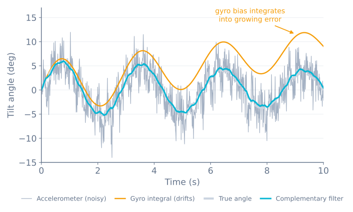
You have an accelerometer that is right on average but wrong right now, and a gyroscope that is right now but wrong over time. The complementary filter is the observation that these two error profiles are opposites, and that you can therefore take the good half of each.
It is one line of arithmetic. It is also, for a self-balancing robot, very nearly always the right answer — a Kalman filter buys you a small accuracy improvement at a large cost in complexity and CPU time on an 8-bit microcontroller.
The idea
Each sensor is reliable in a different frequency band.
- The accelerometer is reliable at low frequency. Averaged over a second it correctly reports where down is; sample it over 10 ms and it mostly reports the robot’s own motion.
- The gyroscope is reliable at high frequency. Over 10 ms its integrated rate is essentially exact; over a minute the accumulated bias has ruined it.
So: low-pass the accelerometer, high-pass the gyro, and add them. The filters are designed so their responses sum to exactly one at every frequency — they complement each other, which is where the name comes from. No band is counted twice and none is missed.
The implementation
const float ALPHA = 0.98;
float angle = 0;

void updateAngle(float accelAngle, float gyroRate, float dt) {
  angle = ALPHA * (angle + gyroRate * dt) + (1.0 - ALPHA) * accelAngle;
}
That is the whole filter. Read it as: take where the gyro says we have moved to since last time, and nudge it 2% of the way toward what the accelerometer currently claims.
The gyro term supplies responsiveness. The small accelerometer term supplies a slow, permanent correction that stops the gyro’s drift accumulating — it constantly pulls the estimate back toward physical truth, gently enough that transient acceleration spikes barely move it.
Choosing the time constant
ALPHA is not an arbitrary knob. It corresponds to a time constant:
τ = (ALPHA · dt) / (1 − ALPHA)τ is the boundary between the bands. Changes faster than τ come from the gyro; slower than τ, the accelerometer wins. At a 5 ms loop and ALPHA = 0.98, τ = 0.245 s — roughly a quarter second of gyro authority before the accelerometer starts to reassert itself.
ALPHA |
τ at dt = 5 ms | Behaviour |
|---|---|---|
| 0.90 | 45 ms | Very quick to correct drift, but robot motion leaks into the angle |
| 0.98 | 245 ms | The usual starting point for a balancing robot |
| 0.995 | 1.0 s | Very smooth, but takes a second to recover from any gyro error |
| 0.999 | 5.0 s | Effectively gyro-only; drift will win |
Note what the formula implies: ALPHA depends on your loop rate. Copy a value from a project running at 100 Hz into your 500 Hz loop and you have silently made your filter five times slower. If your loop timing changes, recompute ALPHA from the τ you actually want rather than keeping the number.
Timing has to be real
dt must be the time that actually elapsed, not the time you intended to elapse:
unsigned long now = micros();
float dt = (now - lastUpdate) / 1000000.0;
lastUpdate = now;
Hardcoding dt = 0.005 because you called delay(5) is a common shortcut that quietly poisons the result — the I²C read alone takes close to a millisecond, so your real loop is 6 ms and every integration is 17% short. The angle then drifts in a way that looks exactly like gyro bias and cannot be calibrated away.
Better still, run the loop from a hardware timer at a fixed rate rather than delay(). A balancing loop needs consistent timing far more than it needs a particular rate.
Getting the signs right
The single most common failure is a sign mismatch between the two sources. If the accelerometer reports +3° for a forward lean and the gyro reports a negative rate for the same motion, the two terms fight: the filter output will lag, jitter, and settle at the wrong value, and no amount of ALPHA tuning will fix it.
Check it directly. Print both accelAngle and the running integral of gyroRate side by side, then tilt the robot slowly forward by hand:
- Both should move in the same direction.
- Both should reach roughly the same magnitude.
If they move oppositely, negate the gyro rate. If they differ by 90°, you are reading the wrong accelerometer axes for the plane your robot falls in.
Why not a Kalman filter?
A Kalman filter is the statistically optimal answer if you know the noise characteristics of your sensors — and it does perform slightly better, particularly during sustained acceleration.
For a balancing robot the difference rarely justifies it. The complementary filter costs one multiply-add, has one tunable parameter with a clear physical meaning, and fails in ways you can diagnose by printing two numbers. A Kalman filter costs matrix arithmetic every cycle, has a covariance matrix to tune, and when it misbehaves the reason is genuinely hard to see.
Get the robot balancing on a complementary filter first. If it balances well, you have your answer. There is a broader treatment of the trade-offs in sensor noise, filtering and fusion.
Verify it before closing the loop
Two checks catch nearly everything, and both take a minute:
Hold it still for two minutes. The filtered angle should stay put. If it creeps, your gyro bias calibration is off — the accelerometer term should be preventing exactly this, so creep means ALPHA is too high for your bias.
Shake it without rotating it. Move the robot bodily side to side, keeping it vertical. The accelerometer alone will swing wildly; the filtered angle should barely move. If the filtered angle swings too, ALPHA is too low and you are trusting the accelerometer during acceleration — precisely the situation it is worst at.
Once the angle holds still when still and stays honest when shaken, it is good enough to balance on. Close the loop in cascaded PID balance control, or watch a tuned loop work in the balance simulator. The same filter shape — a signal that drifts but is smooth, corrected by one that is noisy but bounded — is how an outdoor robot turns a 1 Hz GPS fix into a usable position.
Explore the graph
Part of these builds
Projects and learning paths that include this tutorial.
Further reading