
Tutorial · Intermediate · 35 min
How Stepper Motors Work: Lag Angle and Step Loss
A stepper does not take steps — it drags a rotor behind a rotating field. That explains microstepping, lost steps, and why the motor is not where you think.
The sentence that makes steppers make sense
A stepper motor does not take steps.
That sounds like a trick, but it is the single most useful thing to know about the part. What the driver actually does is rotate a magnetic field inside the motor in small increments. The rotor is a permanent magnet with teeth, and it follows that field the way a compass needle follows a magnet — not because it is told to, but because it is pulled.
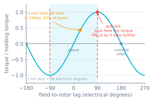
The rotor is therefore always behind the field. It has to be: if it were exactly aligned with the field there would be no force on it, and it could not overcome friction or drive a load. The angle between where the field is pointing and where the rotor actually is has a name — the lag angle, sometimes the load angle — and almost everything a stepper does that surprises people is a fact about that angle.
Written down, the whole model is one line:
T = T_peak × sin(δ)where δ is the lag angle in electrical degrees. Everything below is a consequence.
Electrical degrees, and the 1.8° motor
Steppers are quoted in mechanical degrees — a “1.8° motor” moves 1.8° of shaft rotation per full step, giving 200 full steps per revolution. But the magnetics repeat much faster than the shaft does. A standard hybrid motor has 50 rotor teeth, so the magnetic cycle repeats 50 times per shaft revolution:
| Quantity | Mechanical | Electrical |
|---|---|---|
| One full step | 1.8° | 90° |
| One revolution | 360° | 18 000° (50 cycles) |
| Peak torque at | 7.2° behind | 90° behind |
| Stable range | ±3.6° | ±90° |
The conversion is the only arithmetic you need: one full step is 90 electrical degrees, always, on every 1.8° motor. So the stable range — the range in which the rotor is being pulled back toward where it should be — is exactly ±2 full steps.
Why steppers lose steps
Look again at that sine curve. Between −90° and +90° the motor behaves like a spring: fall further behind, get pulled harder. That is a stable equilibrium and it is why a stepper can run open loop at all, with no encoder and no feedback. The rotor self-corrects.
Past 90°, the sine turns over. Fall further behind now and the torque pulling you forward gets weaker. Which makes you fall further behind still. Which weakens it further — and at 180° the torque changes sign altogether and starts pushing the rotor toward the next pole rather than back to this one. From there the rotor slides until it catches on the next stable tooth, an entire electrical cycle away.
So 90° is where a steady load runs out of road: beyond it there is no equilibrium to sit at, only a slope. A brief excursion past 90° can still be survived if the rotor has the momentum to come back — full stepping does exactly that at every step edge, overshooting to around 100° and recovering each time — but a load that sits past 90° is already falling.
That is a lost step, and it has three properties worth memorising:
- It is silent. There is no encoder. The driver keeps counting pulses, the firmware keeps believing them, and the machine’s idea of where it is is now permanently wrong. Every move after this one is offset.
- It comes in fours. The rotor lands on the next stable point, which is one electrical cycle away — 360 electrical degrees, which is four full steps. A stepper never loses one step. It loses four, or eight, or a hundred.
- It never fixes itself. Losing steps in the other direction later does not cancel it out except by coincidence.
The stepper simulator integrates this directly rather than scripting it: nothing in the code looks for step loss. The rotor’s equation of motion is the sine law above, and when sin(δ) rolls over the rotor falls out of sync on its own — and the reported loss always comes out a multiple of four.
What makes the lag angle grow
Three things, and telling them apart is how you diagnose a machine.
Load. In steady motion, the lag angle settles wherever the torque produced equals the torque demanded:
sin(δ) = torque demanded ÷ peak torque availableA load at 43% of peak sits at 26 electrical degrees. A load at 71% sits at 45°. A load at 100% sits at 90° — right on the cliff, with zero margin. This is why the usual advice is to size a stepper at roughly half its available torque: not for safety factor superstition, but because half torque is 30 electrical degrees of lag and leaves you 60° of margin for the transient you did not model.
Acceleration. Getting the rotor moving takes torque too, and that torque comes out of the same budget. During acceleration the demand is load + J × α, so the lag angle is at its worst on the ramp, not at speed. Tell a motor at rest to run immediately at full speed and the commanded field sprints away while the rotor is still gathering itself — the lag is past 90° within a millisecond or two, and with nothing to pull it back it keeps going and the motor simply buzzes in place. That limit has a name: the pull-in rate, the highest step rate you can command from a standstill without a ramp.
Speed. This one is the least obvious and the most common cause of real-world failures, and it gets its own section.
Torque falls with speed, and holding torque is a marketing number
The number on a motor’s label — “0.44 N·m holding torque” — is measured with the shaft stationary and rated current in the windings. It tells you almost nothing about a motor that is moving.
A winding is an inductor. To make torque, the driver has to force current into it and then reverse that current, over and over, faster and faster as the motor speeds up. Two things fight back:
- Reactance. The winding’s opposition to changing current rises in proportion to electrical frequency, and electrical frequency is 50× shaft speed.
- Back-EMF. A spinning permanent-magnet rotor generates its own voltage, opposing the supply. Past a certain speed the supply simply cannot push current in at all.
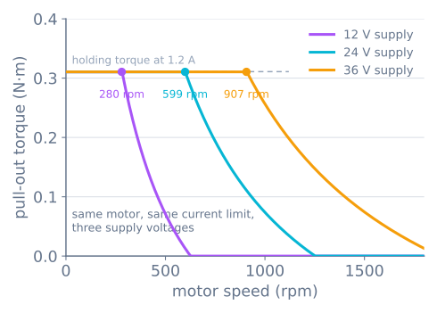
This produces the two rules that matter when a machine will not go fast enough:
| Symptom | What to change | Why |
|---|---|---|
| Stalls under load at low speed | Raise the current limit | Below the corner, current sets torque directly |
| Stalls only at high speed | Raise the supply voltage | Past the corner, voltage is what forces current in |
| Stalls everywhere | Wrong motor, or the load is too big | No setting rescues an undersized motor |
More amps buy torque. More volts buy speed. Turning the current up to fix a high-speed stall does nothing at all, because past the corner the driver was never reaching the set current in the first place — and you get a hot motor for your trouble.
Microstepping: what it does and what it does not
Microstepping means rotating the field in fractions of a full step by mixing the two phase currents, rather than swinging them fully on and off. At 1/16 stepping, one STEP pulse advances the field by 5.625 electrical degrees instead of 90.
What it genuinely fixes is the ringing. The rotor is a mass on a magnetic spring with very little damping. Kick it 90 electrical degrees at a time and it overshoots, oscillates, and settles — audibly and visibly. That is the noise a full-stepping motor makes and the ripple it leaves in a surface finish. Divide the kick by sixteen and the excitation nearly disappears.
You can measure that. Driving the same axis at the same speed with the same load, and recording how far the carriage strays from the commanded path:
| Microstepping | Step size (GT2 belt) | Worst deviation from the path | Steady-state error from load |
|---|---|---|---|
| Full step | 0.200 mm | 0.127 mm | 0.049 mm |
| 1/2 | 0.100 mm | 0.082 mm | 0.045 mm |
| 1/4 | 0.050 mm | 0.061 mm | 0.044 mm |
| 1/8 | 0.025 mm | 0.050 mm | 0.044 mm |
| 1/16 | 0.0125 mm | 0.045 mm | 0.044 mm |
Read those last two columns against each other, because they are the entire argument. Sixteen times the resolution buys about 2.8× better tracking and then stops improving — while the steady-state error caused by the load does not move at all. It is 0.044 mm at full step and 0.044 mm at sixteenth step. The curve in the third column is flattening onto the fourth, and the fourth is not made of resolution.
What microstepping does not fix is the lag angle. Under this load the rotor sits about 20 electrical degrees behind the field, which is 0.4 mechanical degrees, which on this axis is 0.044 mm of position error. At full stepping that is a quarter of a step and nobody notices. At 1/16 stepping the same 0.044 mm is 3.5 microsteps, and the driver is confidently reporting a position it is nowhere near. Dividing the step made the error look bigger in units of steps; it did nothing whatever to the error.
The reason is worth stating plainly. To hold position one microstep away from the detent, the motor produces T_peak × sin(90° ÷ microsteps) — the torque available per microstep collapses as you divide:
| Microstepping | Torque holding one microstep | Fraction of holding torque |
|---|---|---|
| Full step | sin(90°) | 100% |
| 1/8 | sin(11.25°) | 19.5% |
| 1/16 | sin(5.625°) | 9.8% |
| 1/256 | sin(0.352°) | 0.61% |
That last figure matches the number the driver literature quotes for 1/256 stepping, and it is the whole story: at fine divisions, the torque distinguishing one microstep from the next is smaller than the friction in your machine. The rotor physically cannot tell them apart. It moves when the accumulated command is large enough to overcome friction, and then it moves several microsteps at once.
So: microstep for smoothness and quiet, not for accuracy. If you need the position to be right, you need enough torque margin, or you need an encoder.
Seeing it happen
The most useful experiment is the cheapest one. In the stepper simulator, run a 60 mm move twice with everything identical except the ramp:
| With an acceleration ramp | Commanded straight to full speed | |
|---|---|---|
| Peak lag angle | 25° — comfortable | past 90° at 1.2 ms, gone by 3.0 ms |
| Full steps lost | 0 | 280 |
| Where the axis ends up | 60.00 mm | 4.0 mm |
Same motor, same driver, same current limit, same target. The only difference is whether the step rate was ramped, and the difference between them is the entire move. This is why motion profiles are not a refinement on a stepper machine — they are the thing that makes it work at all.
When it goes wrong
| Symptom | Likely cause | What to do |
|---|---|---|
| Motor buzzes loudly and does not turn | Commanded step rate above the pull-in rate | Add an acceleration ramp; check the start speed |
| Drifts a few millimetres per print, always one direction | Losing steps on the ramp | Lower acceleration, raise current, or slow down |
| Fine at low speed, stalls when you speed it up | Past the corner speed | Raise the supply voltage — current will not help |
| Position wrong by a multiple of four full steps | Classic pole slip | Find which move overloads it; the count tells you how many |
| Motor is hot enough to hurt | Current limit too high, or the motor is doing real work | 60–80 °C is normal; check the limit against the rating |
| Rough, noisy, vibrates at one particular speed | Mid-band resonance | Change microstepping, add damping, or avoid that speed |
| Two coils wired as one pair | Wrong wire pairing | Measure resistance: a pair reads a few ohms, a mismatch reads open |
Where this leads
Once the lag angle is in your head, the rest of the stepper world stops being a set of unrelated rules. Setting the current limit on an A4988 is setting T_peak. Choosing a belt or a lead screw is choosing how many electrical degrees a millimetre of error costs you. Homing against an endstop is how an open-loop machine recovers the absolute position it can never measure. And a motion profile is what keeps the lag angle inside ±90° for the whole move.
They are four faces of the same sine curve.
Explore the graph
Part of these builds
Projects and learning paths that include this tutorial.
Further reading