
Tutorial · Beginner · 30 min
A4988 Wiring and Vref: Set the Stepper Current Limit
Wire an A4988 to an Arduino and a NEMA 17, then set the current limit with a multimeter. The Vref formula, the sense resistor trap, and the cost of skipping it.
What the driver is actually for
An A4988 is not a switch. It is a current regulator that happens to switch.
That distinction matters because a stepper winding is a low-resistance inductor — 2 to 4 ohms is typical. Connect a 2.8 Ω winding straight to 24 V and Ohm’s law says 8.6 A, which would destroy the motor in seconds. The driver’s job is to chop the supply on and off thousands of times a second so that the average current settles at a value you choose, and then to swing that current between the two coils in the pattern that makes the field rotate.
So the driver needs to be told one number: how much current per phase. That is the current limit, and setting it is the single adjustment on the board. Everything else — microstepping, direction, enable — is a pin you set once.
Wiring it
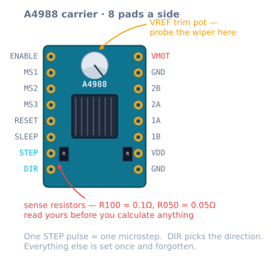
| A4988 pin | Goes to | Note |
|---|---|---|
| VMOT | 8–35 V motor supply | Not the Arduino’s 5 V. Never. |
| GND (next to VMOT) | Motor supply ground | The high-current return |
| VDD | Arduino 5 V | Logic supply, a few milliamps |
| GND (next to VDD) | Arduino GND | Must share ground with the motor supply |
| 1A, 1B | One motor coil | Either way round — it only flips direction |
| 2A, 2B | The other motor coil | Getting the pairing wrong is the fatal error |
| STEP | Any Arduino output | One pulse, one microstep |
| DIR | Any Arduino output | High or low picks the direction |
| ENABLE | GND, or an Arduino pin | Active low: tie low to energise |
| RESET, SLEEP | Joined to each other | Both must be high; jumpering them together does it |
| MS1, MS2, MS3 | See the table below | Floating means full step |
Two wiring rules carry nearly all the risk:
- A 100 µF electrolytic across VMOT and GND, close to the board. Not optional. The datasheet and every carrier’s documentation say so, and the reason is that the chopper draws current in sharp bursts; without bulk capacitance nearby, the inductance of the supply leads turns those bursts into voltage spikes that exceed the chip’s 35 V rating. Boards die on power-up, not during operation, and this is usually why.
- Never unplug the motor while the driver is powered. Interrupting an energised coil produces a large inductive kick with nowhere to go. Power down first, every time.
If the motor’s four wires are not labelled, find the pairs with a multimeter: within a coil you will read a few ohms, and between coils you will read open circuit. Pair them by continuity, then connect one pair to 1A/1B and the other to 2A/2B.
Setting the current limit
There is a pot on the board, and turning it changes a reference voltage the chip compares against the voltage across its sense resistors. You measure that reference — Vref — between the pot’s wiper and ground.
The formula on an A4988 is:
Vref = I_phase × R_sense × 8Here is the trap that costs people motors. R_sense is not the same on every board. Carriers ship with either 0.1 Ω or 0.05 Ω sense resistors, and the formula’s answer differs by a factor of two:
| Sense resistor | Marked on the board | Vref for 1.0 A | Vref for 1.2 A | Vref for 1.5 A |
|---|---|---|---|---|
| 0.1 Ω | R100 |
0.80 V | 0.96 V | 1.20 V |
| 0.05 Ω | R050 |
0.40 V | 0.48 V | 0.60 V |
| 0.068 Ω | R068 |
0.54 V | 0.65 V | 0.82 V |
Read the marking on the two black SMD resistors near the bottom of the board before you calculate anything. Set 1.2 V on a board with 0.05 Ω resistors and you have just asked for 3 A through a 1.7 A motor.
The procedure:
- Power the board — VMOT connected, motor disconnected. The chip needs motor voltage to regulate, but you do not need the motor turning.
- Look up the motor’s rated phase current. A common NEMA 17 is 1.5 A or 1.7 A.
- Take 70–85% of it as your target. Rated current assumes datasheet cooling you do not have, and the last 20% of current buys very little torque while producing a lot of heat.
- Calculate Vref from the formula and the sense resistor you actually have.
- Put the black meter probe on a ground pin and the red probe on the metal screw of the pot. Turn it slowly — a quarter turn is a large change — until the meter reads your number.
A small ceramic screwdriver is worth using. A metal one that bridges the pot to something else while the board is live is a common way to destroy a driver.
Worth stating plainly: the current limit is the T_peak in the torque equation that governs everything a stepper does. Set it low and the motor lags further behind for the same load, and loses steps sooner. Set it high and the motor runs hot for torque it may not need. It is the one number you should be deliberate about.
Microstepping pins
MS1, MS2 and MS3 have internal pull-downs, so anything you leave floating reads low:
| MS1 | MS2 | MS3 | Resolution | Steps per revolution |
|---|---|---|---|---|
| low | low | low | Full step | 200 |
| high | low | low | Half step | 400 |
| low | high | low | Quarter step | 800 |
| high | high | low | Eighth step | 1600 |
| high | high | high | Sixteenth step | 3200 |
Most builds jumper all three high and leave them there. The reason is not accuracy — microstepping does not buy accuracy under load — it is that sixteenth stepping stops the motor ringing at each step, which makes the machine quiet and stops the ripple from showing up in the work. The cost is that your microcontroller now has to issue sixteen times as many pulses per millimetre, which is a real constraint on an Arduino Uno above roughly 10 000 steps per second.
Driving it
The minimum useful sketch. Note there is no library here: a step is a pulse, and that is genuinely all it is.
const int STEP_PIN = 3;
const int DIR_PIN  = 4;
const int EN_PIN   = 5;   // active LOW

void setup() {
  pinMode(STEP_PIN, OUTPUT);
  pinMode(DIR_PIN, OUTPUT);
  pinMode(EN_PIN, OUTPUT);
  digitalWrite(EN_PIN, LOW);      // energise the coils
  digitalWrite(DIR_PIN, HIGH);
}

void loop() {
  // One revolution at 1/16 stepping = 3200 pulses.
  for (int i = 0; i < 3200; i++) {
    digitalWrite(STEP_PIN, HIGH);
    delayMicroseconds(2);         // datasheet minimum is 1 us
    digitalWrite(STEP_PIN, LOW);
    delayMicroseconds(300);       // this delay IS the speed
  }
  delay(1000);
}
That code works and it is also exactly what you should not ship, for two reasons.
The first is that the step rate jumps from zero to full immediately. Ask for a rate above the motor’s pull-in limit and it will buzz and go nowhere — with the defaults in the stepper simulator, commanding full speed from a standstill loses 280 full steps on a 60 mm move and leaves the axis at 4 mm. The same move with a ramp lands exactly on target. That is the difference an acceleration profile makes, and it is not a refinement.
The second is that delayMicroseconds blocks. While the loop is stepping, nothing else on the microcontroller runs — no endstop check, no serial, no second axis. For anything real, use the non-blocking timing pattern or hand it to AccelStepper, which implements the ramp and the scheduling for you:
#include <AccelStepper.h>
AccelStepper axis(AccelStepper::DRIVER, STEP_PIN, DIR_PIN);

void setup() {
  pinMode(EN_PIN, OUTPUT);
  digitalWrite(EN_PIN, LOW);
  axis.setMaxSpeed(8000);        // steps/s  -> 100 mm/s at 80 steps/mm
  axis.setAcceleration(16000);   // steps/s2 -> 200 mm/s2
  axis.moveTo(80 * 50);          // 50 mm
}

void loop() {
  axis.run();                    // returns immediately; call it constantly
}
setMaxSpeed and setAcceleration give you a trapezoidal profile and nothing else — there is no S-curve option. If you want a jerk-limited profile, you generate the setpoint yourself.
A4988 or one of the alternatives?
| Driver | Current | Microstepping | Noise | Pick it when |
|---|---|---|---|---|
| A4988 | 1 A bare, ~1.5 A cooled | to 1/16 | Audible | Cheap, everywhere, well documented |
| DRV8825 | 1.5 A bare, ~2.2 A cooled | to 1/32 | Audible | You need more current or finer steps |
| TMC2208 | ~1.2 A | to 1/256 | Near silent | Noise matters; it is the reason printers moved |
| TMC2209 | ~1.7 A | to 1/256 | Near silent | As above, plus sensorless homing |
| ULN2003 + 28BYJ-48 | ~0.3 A | Half step | Buzzy | A toy-scale demo, not a machine |
The DRV8825 is pin-compatible but its Vref formula is different — Vref = I × 0.5 — and its pot turns the other way. Swapping one in without re-reading the formula is a classic way to cook a motor.
The TMC drivers are worth the money the moment a machine lives somewhere you can hear it. They do the same job with a smoother current waveform, which is why a printer with them makes fan noise instead of motor noise.
When it goes wrong
| Symptom | Cause | Fix |
|---|---|---|
| Motor vibrates but does not rotate | Coil pairs wired wrong | Find the pairs by continuity and re-wire |
| Nothing happens at all | ENABLE floating or high, or RESET/SLEEP low | Tie ENABLE low; jumper RESET to SLEEP |
| Driver gets too hot to touch, then cuts out | Current limit too high | Re-measure Vref; add a heatsink and airflow |
| Motor is hot but the driver is fine | Normal | 60–80 °C on the case is expected |
| Steps lost on fast moves only | Supply voltage too low for that speed | Raise VMOT — more current will not help |
| Steps lost on hard accelerations | Ramp too aggressive, or current too low | Lower acceleration, or raise Vref toward rated |
| Board died the instant it was powered | Missing bulk capacitor on VMOT | 100 µF electrolytic, close to the pins |
| Motor holds position but is rough turning | Full stepping | Jumper MS1–MS3 high for 1/16 |
| Resistance reads open across a “pair” | Those two wires are from different coils | Re-pair them |
Next
With the driver set, the remaining question is how many pulses a millimetre of travel is worth — which depends entirely on what the shaft is turning. That is steps per millimetre, and it is the number every other part of the machine is calibrated against.
Explore the graph
Part of these builds
Projects and learning paths that include this tutorial.
Further reading