
Component · Driver
TB6612FNG Motor Driver
The TB6612FNG is a MOSFET dual H-bridge that drives two DC motors while wasting almost no voltage—the efficient upgrade from an L298N.
What it is
The TB6612FNG is a dual H-bridge motor driver that does the same job as an L298N—standing between a microcontroller’s logic pins and motors that want far more current—but builds its output stage from MOSFETs instead of bipolar transistors. That one change is the whole story: a MOSFET switch drops a few tenths of a volt where the L298N’s stage drops around two.
On a 6 V battery driving 6 V motors, that difference is most of your speed. It is also most of your heat: the L298N wants a heatsink at sustained current, while a TB6612FNG carrier the size of a postage stamp runs merely warm.
How you control it
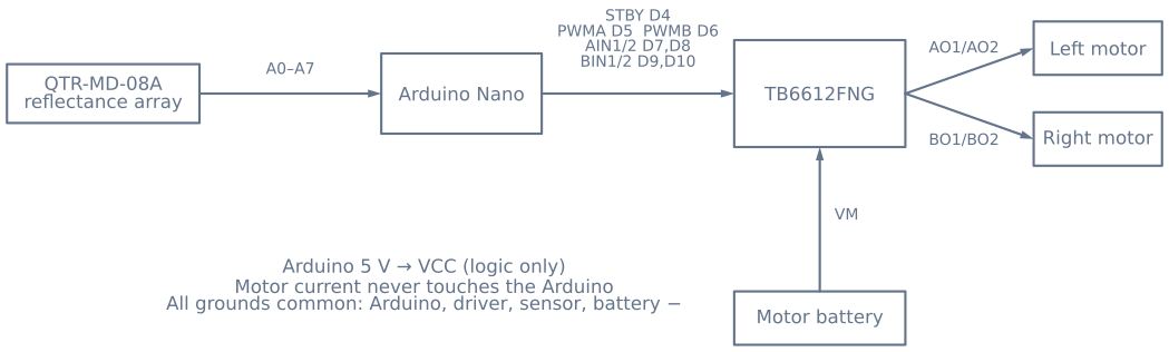
Each motor takes three signals, plus one shared pin for the chip:
- Two direction pins (AIN1/AIN2 for motor A, BIN1/BIN2 for motor B) select forward, reverse, brake, or coast.
- One PWM pin (PWMA or PWMB) sets speed. Unlike the L298N, where PWM rides on an enable pin, the TB6612FNG has a dedicated PWM input per channel that accepts up to 100 kHz—high enough to switch above the audible range so your robot stops whining.
- One STBY pin, shared. Hold it LOW and both bridges are dead regardless of everything else.
That STBY pin is worth repeating, because it costs beginners an evening: a correctly wired TB6612FNG with STBY left floating or LOW does absolutely nothing, silently, with no error to read.
When to use it
Reach for the TB6612FNG when your motors are small and your battery is precious—which describes nearly every line follower and line maze robot. Small robots run at 6–7.4 V, exactly the range where the L298N’s 2 V tax hurts most, and they run on a battery you would rather not waste as heat.
Stay with the L298N when your motor supply exceeds 13.5 V, which the TB6612FNG cannot accept, or when you need more than about 1.2 A continuous per channel.
Wiring and gotchas
- Drive STBY HIGH. The first thing your
setup()should do afterpinMode. - Two supplies, one ground. Motor battery to VM, Arduino 5 V to VCC, and all grounds tied together—Arduino, driver, sensor array, and battery negative. A missing common ground gives control signals no reference, and the failure is silent.
- Respect 13.5 V. There is no on-board regulator and no headroom above the maximum motor supply. A 3S lithium pack at 12.6 V nominal will exceed it when freshly charged.
- A motor spinning the wrong way is a two-second fix. Swap that motor’s two output wires, or invert its direction logic in firmware. Do this before you tune anything else, or you will chase a control bug that is really a wiring one.
Pinout
Two rows on the common SparkFun-style carrier: logic on one side, power and motors on the other.
| Side | Pin | What it does |
|---|---|---|
| Logic | VCC |
Logic supply, 2.7–5.5 V from the microcontroller |
| Logic | GND |
Ground. Every ground on the robot ties here |
| Logic | STBY |
Standby, active low. LOW = both bridges dead, silently |
| Logic | AIN1, AIN2 |
Motor A direction |
| Logic | PWMA |
Motor A speed. Accepts up to 100 kHz |
| Logic | BIN1, BIN2 |
Motor B direction |
| Logic | PWMB |
Motor B speed |
| Power | VM |
Motor supply, 2.5–13.5 V. No regulator, no headroom |
| Power | GND |
Motor ground |
| Motors | AO1, AO2 |
Motor A terminals |
| Motors | AO1, AO2 |
Motor B terminals (BO1, BO2) |
The truth table
STBY |
IN1 |
IN2 |
PWM |
Result |
|---|---|---|---|---|
| LOW | × | × | × | Nothing. Both bridges off, no error, no clue |
| HIGH | HIGH | LOW | PWM | Forward at duty |
| HIGH | LOW | HIGH | PWM | Reverse at duty |
| HIGH | HIGH | HIGH | × | Short brake |
| HIGH | LOW | LOW | HIGH | Stop (coast) |
The top row is the one that costs people an evening. A perfectly wired board with STBY
floating does absolutely nothing, and floating is what an un-driven pin does. Drive it
HIGH in setup(), on the first line after pinMode.
Wiring it to an Arduino
| TB6612FNG | Arduino Uno | Note |
|---|---|---|
VCC |
5 V | Logic only, a few milliamps |
GND |
GND | And to the battery negative, and to every sensor ground |
STBY |
Pin 12 | Or tie to 5 V through a 10 kΩ resistor if you never want to disable it |
PWMA |
Pin 9 | Must be PWM-capable |
AIN1 |
Pin 8 | |
AIN2 |
Pin 7 | |
PWMB |
Pin 3 | Must be PWM-capable |
BIN1 |
Pin 5 | |
BIN2 |
Pin 4 | |
VM |
Motor battery + | 2.5–13.5 V — check a fresh pack’s real voltage |
Minimal working code
const int STBY = 12;
const int PWMA = 9, AIN1 = 8, AIN2 = 7;
const int PWMB = 3, BIN1 = 5, BIN2 = 4;

void setup() {
  for (int p : {STBY, PWMA, AIN1, AIN2, PWMB, BIN1, BIN2}) pinMode(p, OUTPUT);
  digitalWrite(STBY, HIGH);          // without this, nothing happens at all
}

// speed: -255..255
void driveA(int speed) {
  speed = constrain(speed, -255, 255);
  digitalWrite(AIN1, speed > 0);
  digitalWrite(AIN2, speed < 0);
  analogWrite(PWMA, abs(speed));
}

void brakeA() {                       // short brake: both direction pins high
  digitalWrite(AIN1, HIGH);
  digitalWrite(AIN2, HIGH);
}

void loop() {
  driveA(200); delay(1000);
  brakeA();    delay(300);
  driveA(-200); delay(1000);
  brakeA();    delay(300);
}
Getting rid of the whine
This is the TB6612FNG’s quiet superpower and almost nobody uses it. The driver accepts PWM
up to 100 kHz, but an Arduino Uno’s analogWrite runs at 490 Hz on most pins and 980 Hz
on pins 5 and 6 — squarely in the audible band, which is why a robot sings while it drives.
Human hearing tops out around 20 kHz. Push the PWM above that and the noise disappears entirely. On an Uno, pins 9 and 10 are driven by Timer 1, which you can reprogram:
void setup() {
  // Timer1 (pins 9, 10): phase-correct PWM, no prescaler -> ~31.4 kHz
  TCCR1B = (TCCR1B & 0b11111000) | 0x01;
}
That single line moves the switching frequency to about 31 kHz — inaudible, and still well
within the driver’s rating. The cost is that Timer 1 is also what the Servo library uses,
so you cannot do both on the same timer.
An L298N cannot follow you up there; its bipolar stage switches too slowly and the losses climb sharply with frequency. This is a real, practical advantage of the MOSFET stage beyond the efficiency numbers.
What 0.5 V instead of 2 V actually buys
| Supply | L298N delivers | TB6612FNG delivers | Extra available |
|---|---|---|---|
| 6 V (4×AA) | ~4.0 V | ~5.5 V | +38% |
| 7.4 V (2S Li-ion) | ~5.4 V | ~6.9 V | +28% |
| 12 V | ~10.0 V | ~11.5 V | +15% |
The lower your supply, the more the difference matters — which is exactly backwards from where people expect it to matter, and exactly why small robots feel transformed by the swap.
There is a thermal consequence too. At 1 A per channel the L298N dissipates roughly 2 W per channel; the TB6612FNG dissipates around 0.5 W across both. That is the difference between a part needing a heatsink and airflow, and a part you can bury under a chassis plate.
Troubleshooting
| Symptom | Likely cause | Fix |
|---|---|---|
| Absolutely nothing happens | STBY floating or LOW |
Drive it HIGH — this is the first thing to check, every time |
Nothing happens, STBY is high |
No common ground | Tie driver, board, sensors and battery negative together |
| One motor runs backwards | Leads or logic inverted | Swap that motor’s two output wires, or invert its logic |
| Speed is on/off only | PWM pin is not PWM-capable | Use 3, 5, 6, 9, 10 or 11 on an Uno |
| Loud whine while driving | PWM in the audible band | Raise the timer frequency above ~20 kHz |
| Driver got hot and died | VM above 13.5 V |
A fresh 3S pack is 12.6 V and rising; check under charge |
| Motors stutter under load | Supply sagging, or over 1.2 A continuous | Bigger pack, or parallel the two channels for one motor |
| Works on the bench, fails on carpet | Continuous current above rating | Carpet raises load; check current with a meter under real conditions |
Two channels can be paralleled for a single motor — tie AIN1 to BIN1, AIN2 to
BIN2, PWMA to PWMB, and the outputs together — for roughly 2.4 A continuous. The
datasheet supports it, and it is the standard answer when one motor is just over the limit.
When the TB6612FNG is the wrong choice
It is the right default for small robots, and there are three clear cases where it is not.
Above 13.5 V. There is no headroom and no regulator. A 4S pack is out of the question, and a 3S pack needs checking when freshly charged.
Above ~1.2 A continuous per channel, and paralleling the channels does not get you far enough. An L298N manages 2 A per channel with heatsinking, and a BTS7960 goes to 43 A for genuinely large motors.
When you need current sensing or limiting. The DRV8833 is close to the TB6612FNG in every other respect and adds current limiting, which lets the driver protect itself against a stall rather than relying on your code to notice.
Explore the graph
Used in these builds
Projects, learning paths, and simulators that include the TB6612FNG Motor Driver.
- ProjectBuild a GPS Waypoint Rover That Drives Itself
- ProjectBuild a Line Maze Solver Robot With LSRB Route Memory
- ProjectBuild a Mecanum Robot That Drives Sideways
- ProjectBuild a Micromouse: A Flood-Fill Maze-Solving Robot
- ProjectBuild a Mini Sumo Robot: Grip, Wedge and Edge Sense
- ProjectBuild a Room Coverage Robot That Sweeps a Floor
- ProjectBuild a ROS 2 Robot That Sees and Drives to a Marker
- ProjectBuild a Self-Balancing Robot With an MPU6050 and PID
- Learning pathMotor Control for Robots: A Learning Roadmap
Compare
Alternatives
Questions
TB6612FNG Motor Driver FAQ
What is the TB6612FNG motor driver?
The TB6612FNG is a dual H-bridge motor driver built from MOSFETs rather than the older bipolar transistors. It takes low-power direction and PWM signals from a microcontroller and switches a separate motor supply to drive two DC motors independently, delivering 1.2 A continuously per channel with 3.2 A peaks.
Is the TB6612FNG better than the L298N?
For small robot motors, yes. The L298N's transistor output stage drops roughly 2 V before the motor sees anything, so a 6 V motor on a 6 V pack runs weak and the chip needs a heatsink. The TB6612FNG's MOSFET stage drops a few tenths of a volt, runs cool without a heatsink, and is far smaller. The L298N still wins when you need more than 13.5 V of motor supply, which the TB6612FNG cannot accept.
How do you wire a TB6612FNG to an Arduino?
Motor battery positive to VM, Arduino 5 V to VCC, and every ground tied together—Arduino, driver, sensors and battery negative. Then STBY to a digital pin, and per motor two direction pins (AIN1/AIN2 or BIN1/BIN2) plus one PWM pin (PWMA or PWMB). Motors connect to the AO1/AO2 and BO1/BO2 terminals.
What does the STBY pin do on a TB6612FNG?
STBY is a standby enable for the whole chip. Held LOW, both bridges are disabled and the motors coast no matter what the other pins say. You must drive it HIGH before anything moves—forgetting it is the single most common reason a freshly wired TB6612FNG does nothing at all.
How much current can a TB6612FNG handle?
1.2 A continuous per channel, with short peaks up to 3.2 A. That comfortably covers the small yellow gear motors and N20 motors used in line followers and maze robots. Larger motors that stall above 1.2 A will trip its thermal shutdown, so step up to a driver such as the DRV8871 or a proper brushed ESC instead.
Further reading