
Tutorial · Beginner · 45 minutes
Reading Tilt Angle From an MPU6050 Accelerometer and Gyro
Wire an MPU6050 to an Arduino and turn raw accelerometer and gyroscope counts into a tilt angle in degrees, including the offsets nobody warns you about.
Introduction
The MPU6050 is the cheapest honest answer to “which way is up”. It contains two independent sensors on one die — a three-axis accelerometer and a three-axis gyroscope — and a self-balancing robot needs both, because each one is useless on its own in a way the other exactly compensates for.
This tutorial gets you from a bare module to a tilt angle in degrees that you can trust while the robot is standing still. Making that angle survive the robot moving is the complementary filter, which is the next tutorial and depends on everything here.
What each sensor actually measures
An accelerometer does not measure tilt. It measures acceleration, including the acceleration due to gravity, which is why it works as a tilt sensor at all: sitting still, the only acceleration is 1 g pointing down, and the way that vector distributes across the axes tells you your orientation.
That “sitting still” is the catch. The sensor cannot distinguish gravity from any other acceleration. The instant your robot’s wheels move, the accelerometer reports the vector sum of gravity and the robot’s own motion, and reads a tilt that is not there. On a balancing robot — which by definition never stops accelerating — this error is continuous.
A gyroscope measures angular rate, in degrees per second. Integrate the rate over time and you get an angle. Gyros are immune to linear acceleration, so they stay honest while the robot moves.
Their weakness is that integration accumulates error. Any small constant bias in the rate reading integrates into an angle that grows without limit. A gyro reading 0.5 °/s while perfectly still will claim you have rotated 30° after a minute. This is drift, and it is not fixable by better soldering.
So: the accelerometer is right in the long run but wrong at any instant; the gyro is right at any instant but wrong in the long run. That symmetry is the entire reason sensor fusion exists.
Wiring
The MPU6050 speaks I²C, so it needs four wires — and if the scanner does not find it at 0x68, that page explains why its datasheet says 0xD0.
| MPU6050 | Arduino Uno / Nano | Notes |
|---|---|---|
VCC |
5V |
Most breakout boards carry a 3.3 V regulator; check yours before assuming |
GND |
GND |
Must be common with the motor driver ground |
SDA |
A4 |
I²C data |
SCL |
A5 |
I²C clock |
INT |
D2 |
Optional — lets the sensor tell you a sample is ready |
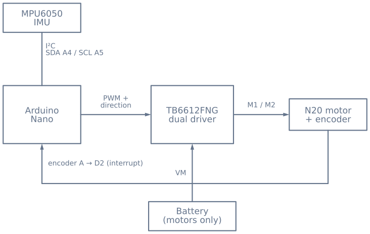
On a balancing robot, mount the module so one of its axes is genuinely horizontal and as close to the wheel axle as you can manage. Mounting it high multiplies the linear acceleration it sees during a correction, which makes the fusion problem harder for no benefit.
Reading raw values
The registers you need are consecutive, so a single burst read gets everything:
#include <Wire.h>

const uint8_t MPU = 0x68;        // 0x69 if AD0 is tied high

void setup() {
  Serial.begin(115200);
  Wire.begin();
  Wire.beginTransmission(MPU);
  Wire.write(0x6B);              // PWR_MGMT_1
  Wire.write(0);                 // clear sleep bit — it boots asleep
  Wire.endTransmission(true);
}

void readRaw(int16_t& ax, int16_t& ay, int16_t& az,
             int16_t& gx, int16_t& gy, int16_t& gz) {
  Wire.beginTransmission(MPU);
  Wire.write(0x3B);              // ACCEL_XOUT_H
  Wire.endTransmission(false);
  Wire.requestFrom(MPU, (uint8_t)14, (uint8_t)true);

  ax = Wire.read() << 8 | Wire.read();
  ay = Wire.read() << 8 | Wire.read();
  az = Wire.read() << 8 | Wire.read();
  Wire.read(); Wire.read();      // temperature, discarded
  gx = Wire.read() << 8 | Wire.read();
  gy = Wire.read() << 8 | Wire.read();
  gz = Wire.read() << 8 | Wire.read();
}
The module boots asleep. Forgetting to clear the sleep bit in PWR_MGMT_1 returns a steady stream of zeros, which reads exactly like a wiring fault and sends people back to their soldering iron for no reason.
Converting counts to units
Raw values are signed 16-bit counts across whatever range the sensor is configured for. At the default settings:
- Accelerometer: ±2 g over ±32768 counts → 16384 counts per g
- Gyroscope: ±250 °/s over ±32768 counts → 131 counts per °/s
float accelX = ax / 16384.0;     // g
float rateY  = gy / 131.0;       // degrees per second
Tilt from the accelerometer
With the robot upright and the board mounted vertically, the tilt angle in the plane the robot falls in comes from two of the three axes:
float pitch = atan2(accelX, accelZ) * 180.0 / PI;Use atan2, not asin of a single axis. atan2 takes both components, so it stays correct through all four quadrants and does not blow up as one axis approaches zero. A single-axis asin version looks fine on the bench at small angles and then behaves strangely the first time the robot leans past 45°.
Calibrating the offsets
Every MPU6050 has a manufacturing offset. Your gyro will not read zero while stationary, and your accelerometer will not read exactly 1 g on one axis and zero on the others. Measure the error once at startup, with the robot held still:
float gyroBiasY = 0;

void calibrate() {
  const int samples = 1000;
  long total = 0;
  for (int i = 0; i < samples; i++) {
    int16_t ax, ay, az, gx, gy, gz;
    readRaw(ax, ay, az, gx, gy, gz);
    total += gy;
    delay(2);
  }
  gyroBiasY = (total / (float)samples) / 131.0;
}
Subtract gyroBiasY from every subsequent rate reading. This single step is the difference between a gyro that drifts a degree a minute and one that drifts a degree a second.
Two things to know about it. The sensor must be genuinely stationary during calibration — a robot calibrating while you hold it will bake your hand tremor into the bias. And the bias changes with temperature, so a robot calibrated cold will drift slightly as the electronics warm up. For a balancing robot the integral term in the control loop absorbs that residual, which is one of the reasons balancing controllers almost always need an I term.
Mounting trim is not the same as sensor bias
There is a second offset that calibration cannot remove: your IMU is not mounted perfectly. If the board sits 1.5° off true vertical, a perfectly calibrated sensor will still report 1.5° when the robot is genuinely upright.
This matters enormously on a balancing robot, and it is invisible on the bench. The control loop will faithfully hold the angle you tell it is upright — so a 1.5° error means the robot holds a permanent 1.5° lean, which means constant acceleration, which means it drives across the room until it hits something.
Measure it by standing the robot up by hand, genuinely balanced, and recording what the angle reads. Subtract that number as a constant. You can watch this exact failure in the balance simulator — the trim slider injects a mounting error and the robot drifts away while insisting it is level.
Verify before you build on it
Print the angle and check three things by hand:
- Upright reads near zero. If not, you have mounting trim to subtract.
- Tipping the robot forward increases the angle, and backwards decreases it. If the sign is inverted, swap it here rather than compensating in the control loop, where it will confuse you later.
- The reading is stable while still, and immediate when moved. Noisy while still means check your wiring and power; laggy means you are averaging too aggressively somewhere.
Once the angle is trustworthy at rest, you are ready to make it trustworthy in motion with the complementary filter, and then to close the loop in cascaded PID balance control.
Explore the graph
Part of these builds
Projects and learning paths that include this tutorial.
Further reading