
Component · Sensor
IR Reflectance Sensor Array
An IR reflectance sensor array is how a line-following robot sees the line. How reflective infrared sensing works, how to calibrate it, and where it fails.
What it is
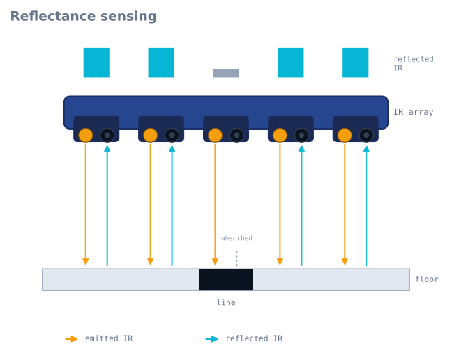
An IR reflectance sensor array is a strip of small infrared sensors mounted in a row, pointed at the ground. Each sensor pairs an infrared LED that shines light down with a phototransistor that measures how much of that light bounces back. Point it at a dark line on a light floor and the line reflects less—so the sensor over the line reads differently from the ones over the floor. Read the whole row and you know not just whether you are on the line, but where the line sits under the robot.
It is the eye of nearly every line-following robot, and the reason the line follower is such a good first project: the sensing is cheap, intuitive, and immediately visible.
How it works
Each channel is an emitter-detector pair. The IR LED emits invisible ~940 nm light; the phototransistor conducts more as more light returns. A white or light surface reflects strongly (high return); a black line absorbs the IR (low return). Two output styles exist:
- Analog — each channel reports a continuous value proportional to reflectance. This is richer: you can compute where between two sensors the line falls and get a smooth error signal for a PID controller.
- Digital — an on-board comparator reports a simple line/no-line per channel. Easier to read, but coarser.
To turn the array into a steering signal, you compute a weighted average of which sensors see the line. If the line drifts under the left sensors, the average shifts left, and that offset becomes the error your control loop corrects.
When to use it
Use a reflectance array whenever a robot must track a high-contrast path—a black line on white, or white tape on a dark floor. More channels give finer position resolution and let the robot handle curves and gaps more gracefully; five is enough to learn on, eight is comfortable for faster or twistier tracks.
It is the wrong tool for detecting objects, distance, or anything off the ground plane—that’s the job of an ultrasonic or time-of-flight sensor.
Calibration and gotchas
- Always calibrate. Ambient light, surface, and ride height all shift the readings. Before a run, sweep the array over both the line and the floor and record the min/max per channel, then scale readings between them. Skipping this is the number-one reason a line follower works on one table and fails on another.
- Height matters. Reflectance sensors have a narrow sweet spot (a few millimetres). Mount the array too high and contrast collapses.
- Ambient IR is noise. Sunlight and some lighting flood the detectors with infrared. Shroud the sensors or run indoors for consistent behaviour, and filter the signal—see taming sensor noise.
- Surface finish lies. Glossy black can reflect like white at the wrong angle; matte tape on matte floor is the reliable combination.
Wiring it to an Arduino
An analog array needs one ADC pin per channel, which is why an 8-channel array and an Uno (six analog pins) is an awkward pairing — a Nano’s eight (A0–A7) fits exactly.
| Array pin | Arduino | Note |
|---|---|---|
VCC |
5 V | The emitters are the current draw, not the detectors |
GND |
GND | |
OUT1–OUT8 |
A0–A7 | Analog channels, one per sensor |
LEDON / CTRL |
Any digital pin | Optional: switches the emitters on and off |
That LEDON pin is worth wiring even though most projects ignore it. An 8-channel array’s
emitters can draw 100–200 mA together, continuously, which on a small battery is a
significant fraction of the budget — and it lets you do ambient-light subtraction, below.
Calibration: the code that decides whether it works
This is not optional and it is not a refinement. An uncalibrated array is the single most common reason a line follower works on the kitchen table and fails at a competition.
const int N = 8;
const int PIN[N] = {A0, A1, A2, A3, A4, A5, A6, A7};
int lo[N], hi[N];

void calibrate() {
  for (int i = 0; i < N; i++) { lo[i] = 1023; hi[i] = 0; }

  // Sweep the array across the line and the floor for ~3 seconds.
  unsigned long start = millis();
  while (millis() - start < 3000) {
    for (int i = 0; i < N; i++) {
      int v = analogRead(PIN[i]);
      if (v < lo[i]) lo[i] = v;
      if (v > hi[i]) hi[i] = v;
    }
  }
}

// 0 = floor, 1000 = line, per channel, normalised against this run's own extremes.
int normalised(int i) {
  int span = hi[i] - lo[i];
  if (span < 50) return 0;                       // this channel never saw contrast
  return constrain(map(analogRead(PIN[i]), lo[i], hi[i], 0, 1000), 0, 1000);
}
Notice the span < 50 guard. A channel that saw no contrast during calibration — because the
sweep missed it, or its emitter is dead — would otherwise produce enormous normalised values
from tiny noise, and the robot would swerve toward a sensor that is telling it nothing.
From eight readings to one steering number
The weighted average is the whole trick, and it produces a continuous position rather than a discrete “sensor 3 sees it”:
// Returns position in the same units as the weights: 0..7000 for an 8-channel array,
// or -1 if the line is not visible at all.
long linePosition() {
  long weighted = 0, total = 0;
  for (int i = 0; i < N; i++) {
    int v = normalised(i);
    if (v > 100) {                    // ignore channels that are clearly on floor
      weighted += (long)v * i * 1000;
      total    += v;
    }
  }
  if (total == 0) return -1;          // line lost
  return weighted / total;
}

// Error for the control loop: 0 when centred.
long error() {
  long pos = linePosition();
  if (pos < 0) return LAST_ERROR;     // hold the last known direction, do not zero it
  return pos - 3500;                  // centre of an 8-channel array
}
Two design decisions in there matter more than the arithmetic:
Ignoring channels below a threshold stops floor noise from dragging the average. Without it, eight channels each reading a small non-zero value pull the estimate toward the middle regardless of where the line is.
Returning the last error when the line is lost — rather than zero — is what lets a robot recover from a sharp corner. Zero means “perfectly centred”, so a robot that zeroes on line loss drives straight on at full speed, away from the line it just lost. Holding the last error means it keeps turning the way it was already turning, which is where the line went.
Mounting height, and why it decides everything
Reflectance sensors have a narrow sweet spot. The signal falls off fast in both directions: too high and the return is weak, too low and the emitter’s cone has not spread enough to illuminate what the detector sees.
| Ride height | Typical behaviour |
|---|---|
| 1–3 mm | Best contrast, but scrapes on any surface irregularity |
| 3–8 mm | The usable band — most arrays specify around 3 mm |
| 8–15 mm | Contrast collapsing; calibration span shrinks |
| > 15 mm | Effectively blind on most surfaces |
Two practical consequences. Mount it rigidly — an array on a flexible bracket changes height as the robot accelerates, which changes the readings, which the control loop reads as the line moving. And mount it level, because a tilted array gives each channel a different effective height and therefore a different calibration, which shows up as a robot that tracks well in one direction and poorly in the other.
Mounting it ahead of the wheels also matters: the further forward, the earlier the robot sees a corner, and the more lead time the controller has. Too far forward and the geometry amplifies the error into oscillation.
Beating ambient light
Sunlight contains a great deal of 940 nm infrared, and it arrives at the detector looking exactly like a reflection. A robot that works indoors and fails near a window is almost always seeing this.
If your array’s emitters can be switched, the fix is complete and costs two readings:
int ambientSubtracted(int i) {
  digitalWrite(LEDON, LOW);   delayMicroseconds(200);
  int dark = analogRead(PIN[i]);      // ambient only
  digitalWrite(LEDON, HIGH);  delayMicroseconds(200);
  int lit  = analogRead(PIN[i]);      // ambient + our own emitter
  return lit - dark;                  // just our emitter
}
Anything constant in the environment cancels exactly. It doubles the sampling time, which on a fast line follower is a real cost — but it turns an unreliable sensor into a reliable one, and it is the technique commercial arrays use.
Failing that: shroud the array with a skirt so it sees only the floor directly beneath it.
Troubleshooting
| Symptom | Likely cause | Fix |
|---|---|---|
| Works on one surface, not another | No calibration, or stale calibration | Recalibrate at the start of every run, on the actual surface |
| Robot swerves toward one side | One channel’s calibration span is wrong | Check every channel’s hi/lo; a dead emitter shows as a tiny span |
| Loses the line on tight corners | Array too close to the wheels, or zeroing on loss | Move it forward; hold the last error rather than zeroing |
| Oscillates on straights | Array too far forward, or gain too high | Reduce lead; retune the controller |
| Fails near a window | Ambient infrared | Emitter-off subtraction, or shroud the array |
| Erratic on glossy black tape | Specular reflection off the tape | Matte tape on matte floor is the reliable combination |
| Readings drift as the run goes on | Battery sagging, so emitters dim | Emitters are current-hungry; check the rail under load |
| All channels read the same | Array too high | Bring it to 3–8 mm and recalibrate |
Choosing an array
| Channels | Position resolution | Good for |
|---|---|---|
| 3 | Coarse — essentially left/centre/right | Learning the concept only |
| 5 | Adequate | A first line follower on a gentle track |
| 8 | Comfortable | Fast tracks, tight curves, line maze junction detection |
| 12–16 | Fine | Competition robots at speed |
Analog beats digital for anything with a control loop. A digital array’s comparator gives you line/no-line per channel, which quantises the position into a handful of discrete values and makes smooth proportional steering impossible. Analog gives a continuous error signal, which is what a PID controller needs.
Channel spacing matters as much as count: the array should be wider than the line by enough that at least one sensor is always on the floor at each edge, but not so wide that the line can sit between two sensors unseen. For standard 19 mm electrical tape, 8 mm spacing works well.
For a line maze solver there is one extra requirement: the array must be wide enough to see a junction. A robot detects a left turn by noticing that the outermost left sensors have gone dark while the centre is still on the line — which is impossible if the array is barely wider than the tape.
Explore the graph
Used in these builds
Projects, learning paths, and simulators that include the IR Reflectance Sensor Array.
Questions
IR Reflectance Sensor Array FAQ
What is a line follower sensor?
A line follower sensor is an infrared reflectance sensor that a robot points at the ground to detect a marked line. Each channel shines IR light down and measures how much bounces back, so a dark line (which reflects less) reads differently from the surrounding floor.
How does a line follower sensor work?
Each channel pairs an IR LED with a phototransistor. Light surfaces reflect strongly and dark lines absorb the infrared, so the sensor over the line reads low while the others read high. Reading the whole row tells the robot where the line sits underneath it.
How do you calibrate an IR sensor for a line follower robot?
Before a run, sweep the array over both the line and the bare floor and record the minimum and maximum reading per channel, then scale live readings between those limits. Skipping calibration is the top reason a line follower works on one surface and fails on another.
What is PID in a line follower?
PID is the control method that turns the sensor's position error into smooth steering. The proportional term reacts to how far off the line the robot is, the derivative term damps overshoot, and the integral term removes steady drift—so the robot tracks the line without wobbling. You can tune it live in our PID simulator.
What are the main components of a line follower robot?
A basic line follower needs four things: an IR reflectance sensor array to see the line, a microcontroller such as an Arduino Uno to run the control loop, a motor driver like the L298N, and two DC motors with wheels. A battery and chassis complete the build.
What is a line follower sensor array used for?
Beyond line-following robots, reflectance arrays are used for edge detection (stopping at a table edge), encoder-style position sensing, and simple surface or contrast detection in automation. Anywhere a robot must react to a high-contrast mark on a surface, a reflectance array is a cheap, reliable choice.
Further reading