
Tutorial · Intermediate · 45 min
From cmd_vel to Wheel Speeds: ROS 2 Differential Drive
Turn a ROS 2 Twist message into left and right wheel commands: inverse kinematics, calibrating wheel separation, handling saturation, and a command watchdog.
Introduction
Everything above the wheels in a ROS 2 robot — teleop, navigation, your own docking controller — speaks the same language: a geometry_msgs/msg/Twist on /cmd_vel, saying “go this fast forward and turn this fast”. Everything below the wheels speaks PWM duty cycles.
This tutorial is the piece in between, and it is short enough to look trivial. Two lines of algebra convert one to the other. The other 90% of a working drive node is what those two lines do wrong when the robot is asked for something it cannot deliver.
What a Twist actually says
Only two of its six numbers matter to a differential-drive robot:
linear.x— forward speed in metres per second, along the robot’s nose.angular.z— yaw rate in radians per second, positive counter-clockwise seen from above.
The other four describe motion a two-wheeled robot cannot perform. linear.y is sideways, which only a holonomic base can do; ignore it rather than approximating it. Swap the two lines below for the four-row mecanum matrix and linear.y starts meaning something. Both values are expressed in the robot’s own base_link frame, and both are in SI units — a robot that takes linear.x as a percentage will look like it works right up until it meets a real navigation stack.
The two lines of kinematics
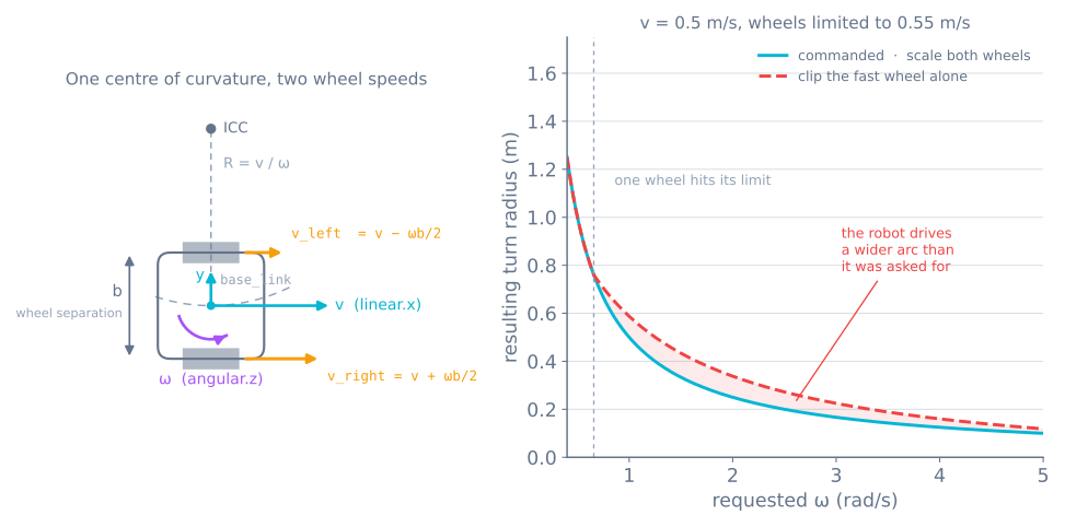
Let b be the wheel separation and v, ω the commanded linear and angular velocity. Each wheel’s ground speed is the robot’s forward speed plus or minus the contribution of the turn:
v_left  = v − ω · b / 2
v_right = v + ω · b / 2
Convert each to a wheel angular velocity by dividing by the wheel radius r:
ω_wheel = v_wheel / r [rad/s]That is the whole conversion. Spinning in place is v = 0, which gives two equal and opposite wheel speeds; driving straight is ω = 0, which gives two identical ones. The ratio between them fixes the turn radius, R = v / ω, and preserving that ratio is what the rest of this tutorial is about.
Measure b by driving, not with a ruler
Wheel separation is the parameter everything else inherits, and the distance between your wheel centres is not it.
The tyres are compliant, they contact the ground over a patch rather than a line, and both scrub sideways through every turn. The value that makes the equations true — the effective track width — is typically a few percent away from the physical one, and always in the direction that makes your robot under-rotate.
Calibrate it directly:
- Command a pure rotation,
v = 0,ω = 1.0 rad/s, for exactly 10 seconds. - The robot should have turned 10 radians — one full turn plus about 213°. Mark the start heading and measure where it actually stopped.
- Scale:
b_new = b_old × (turned / commanded).
Repeat in both directions and average, because an asymmetric drivetrain gives different answers each way. Two iterations is usually enough. This same number is what your odometry uses to integrate position, so calibrating it here fixes two things at once.
Handle saturation without changing the turn
A motor has a top speed. Ask for v = 0.5 m/s with a hard turn on a robot whose wheels top out at 0.55 m/s, and one wheel’s target lands above what it can do.
The obvious response is to clamp that wheel. Do not. Clamping one wheel changes the difference between the wheels, and the difference is the turn — so the robot quietly drives a wider arc than the one that was commanded. A path follower asking for a specific curve gets a different curve back, corrects, saturates again, and weaves.
Scale both wheels by the same factor instead. The ratio survives, so the arc survives; the robot simply traverses it more slowly:
peak = max(abs(left), abs(right))
if peak > MAX_WHEEL_SPEED:
    scale = MAX_WHEEL_SPEED / peak
    left *= scale
    right *= scale
Three lines, and it converts “wrong shape” into “right shape, slower” — which is nearly always the trade you want on a robot that is following something.
Know the envelope you actually have
Scaling saves the arc, but it is worth knowing in advance which commands will trigger it, because that boundary is a property of your robot and a planner can be told about it.
Set v_left or v_right equal to the wheel’s top speed and solve. The largest yaw rate available at a given forward speed is:
w_max(v) = 2 * (V_max - |v|) / bFor the robot in the code below — b = 0.152 m, wheels topping out at 0.55 m/s:
| Forward speed | Max yaw rate | Same in deg/s | Tightest turn radius |
|---|---|---|---|
| 0.00 m/s | 7.24 rad/s | 415 | Spin in place |
| 0.10 m/s | 5.92 rad/s | 339 | 1.7 cm |
| 0.20 m/s | 4.61 rad/s | 264 | 4.3 cm |
| 0.30 m/s | 3.29 rad/s | 188 | 9.1 cm |
| 0.40 m/s | 1.97 rad/s | 113 | 20.3 cm |
| 0.50 m/s | 0.66 rad/s | 38 | 76.0 cm |
| 0.55 m/s | 0 | 0 | Straight only |
The shape is the useful part: speed and turn rate trade linearly, and the last 10% of forward speed costs almost all of your steering. A robot commanded at 0.5 m/s has 12% of the yaw authority it had at a standstill, which is exactly why a path follower that saturates tends to do it in a corner.
Two consequences worth acting on. Put your real limits into the planner rather than letting it discover them by saturating — in Nav2 that is max_vel_x and max_vel_theta, and setting max_vel_x to the full 0.55 m/s guarantees the controller will ask for arcs the robot cannot drive. And when tuning pure pursuit, remember that a lookahead short enough to demand a tight radius will silently cap your speed instead.
Ramp the command, or the wheels slip
A Twist is a step. Navigation publishes 0.0 then 0.35 m/s on consecutive messages, and a step command asks the motors for as much acceleration as they can produce — which on a light robot is more than the tyres can transmit.
What breaks is not the motion, it is the odometry. A slipping wheel turns without the robot moving, the encoders count it anyway, and the pose estimate gains error that no downstream filter can distinguish from real motion. The traction page puts a measured ceiling on this: a robot with 55% of its weight on the drive axle manages about 1.6 m/s2 on dusty tile before the wheels break away.
Limit acceleration below that ceiling, in the timer where dt is known and constant:
MAX_ACCEL = 1.0        # m/s^2 at the wheel, comfortably under the traction limit

def slew(target, current, dt):
    step = MAX_ACCEL * dt
    return max(current - step, min(current + step, target))

# in tick(), before sending:
self.out_left = slew(self.left, self.out_left, 0.02)
self.out_right = slew(self.right, self.out_right, 0.02)
At 1.0 m/s2 a standing start reaches full speed in 0.55 s, adding 20 mm/s per 50 Hz tick. That is slow enough to keep the tyres stuck and fast enough that no human calls the robot sluggish.
Ramp both wheels with the same limit, not the same fraction. Clamping each wheel’s acceleration independently distorts the ratio during the ramp for the same reason per-wheel clipping does — the turn comes out wrong for the first half second of every move, which is precisely when a docking controller is most sensitive.
A complete drive node
import rclpy
from rclpy.node import Node
from geometry_msgs.msg import Twist

WHEEL_RADIUS = 0.0325        # m
WHEEL_SEPARATION = 0.152     # m — calibrated by driving, see above
MAX_WHEEL_SPEED = 0.55       # m/s at full duty, measured
CMD_TIMEOUT = 0.4            # s


class DiffDrive(Node):
    def __init__(self):
        super().__init__('diff_drive')
        self.create_subscription(Twist, 'cmd_vel', self.on_cmd, 10)
        self.create_timer(0.02, self.tick)          # 50 Hz output
        self.left = self.right = 0.0
        self.last_cmd = self.get_clock().now()

    def on_cmd(self, msg):
        v, w = msg.linear.x, msg.angular.z
        left = v - w * WHEEL_SEPARATION / 2.0
        right = v + w * WHEEL_SEPARATION / 2.0

        peak = max(abs(left), abs(right))
        if peak > MAX_WHEEL_SPEED:                  # keep the arc, lose the speed
            left *= MAX_WHEEL_SPEED / peak
            right *= MAX_WHEEL_SPEED / peak

        self.left, self.right = left, right
        self.last_cmd = self.get_clock().now()

    def tick(self):
        age = (self.get_clock().now() - self.last_cmd).nanoseconds * 1e-9
        if age > CMD_TIMEOUT:                       # nobody is driving — stop
            self.left = self.right = 0.0
        send_wheel_targets(self.left / WHEEL_RADIUS,
                           self.right / WHEEL_RADIUS)   # rad/s
Two structural choices are worth naming.
Output on a timer, not in the callback. The motors are commanded at a fixed 50 Hz regardless of how often cmd_vel arrives. A publisher that stutters — because Wi-Fi hiccuped, or a planner took a long cycle — no longer stutters the wheels.
The watchdog is not optional. Without it, the last command before a dropped link is the command the robot keeps executing, and the last command is usually “forward”. A robot that stops when it stops being told what to do is the difference between a bug and a hole in the wall. The wireless control tutorials make the same argument for the same reason.
Turning wheel speed into duty cycle
The node above hands off rad/s per wheel. Something has to make that happen, and there are two honest ways.
Open loop. Map speed to duty linearly and accept the error. Motors have a deadband — below roughly 15–20% duty they buzz and do not turn — so the map has to start above it:
int dutyFor(float radPerSec) {
  if (fabsf(radPerSec) < 0.05f) return 0;                 // genuinely stopped
  float u = fabsf(radPerSec) / MAX_RAD_PER_SEC;           // 0..1
  int duty = DEADBAND + (int)((255 - DEADBAND) * u);
  return (radPerSec > 0) ? duty : -duty;
}
This is fine for teleop and wrong for anything that measures where it went. Duty is a request for torque, not speed: the same duty gives a different speed uphill, on carpet, or with a flat battery.
Closed loop. Put quadrature encoders on the wheels and run a PID loop per wheel with rad/s as the setpoint. Now the drive layer delivers the speed it was asked for, and the deadband, the load, and the battery all become the controller’s problem rather than yours.
On a Pi-based robot the usual split is to run the ROS node on the Pi and the per-wheel PID on an Arduino over serial, at a few hundred hertz. Linux is not the place for a loop that must not jitter.
Test it before the robot can hurt itself
The whole node is testable from the command line with the wheels off the ground. Do that first; a kinematics sign error discovered on a bench is a curiosity, and the same error discovered on a table edge is a repair.
# Straight ahead at 0.2 m/s, republished at 10 Hz
ros2 topic pub /cmd_vel geometry_msgs/msg/Twist \
  '{linear: {x: 0.2}, angular: {z: 0.0}}' -r 10

# Pure rotation, counter-clockwise at 1 rad/s
ros2 topic pub /cmd_vel geometry_msgs/msg/Twist \
  '{linear: {x: 0.0}, angular: {z: 1.0}}' -r 10

# Who is on the topic, and with which message type
ros2 topic info /cmd_vel --verbose
Four checks, in order:
- Straight command, both wheels the same direction and speed. If they differ, the wiring or the sign convention is wrong before any maths is involved.
- Positive
angular.z, left wheel backwards. REP 103 says positive yaw is counter-clockwise seen from above, so the left wheel must run in reverse. Getting this backwards makes every navigation stack steer away from its goal. - Kill the publisher with Ctrl-C. The wheels must stop within
CMD_TIMEOUT. Time it — a watchdog that is never exercised is a watchdog you should assume is broken. - Command past the envelope, say
linear.x: 0.5withangular.z: 3.0, and confirm both wheels scale rather than one clipping. The ratio between the two wheel speeds should be unchanged from the unsaturated command.
Only then put it on the floor, and drive the rotation calibration from the section above as the first real test.
Twist or TwistStamped?
Worth knowing before it costs you an evening: newer parts of the ROS 2 ecosystem — diff_drive_controller among them — have moved to geometry_msgs/msg/TwistStamped, which wraps the same twist in a header carrying a timestamp and frame id.
The failure is silent. A teleop node publishing plain Twist and a controller subscribing to TwistStamped are, as far as DDS is concerned, using two different topics that happen to share a name. Nothing errors; the robot simply never moves. Check with ros2 topic info /cmd_vel --verbose, which prints the type on each end.
When it goes wrong
| Symptom | Usually |
|---|---|
| Robot moves but never turns the commanded amount | Wheel separation not calibrated |
| Turns are fine slow, too wide fast | Per-wheel clipping instead of scaling both |
| Crawls or buzzes at low speed | Deadband not compensated |
| Keeps driving after teleop is closed | No watchdog |
| Publishes fine, robot never moves | Twist against TwistStamped, or a topic namespace mismatch |
| Straight commands drift to one side | Open loop with mismatched motors — needs encoders |
| Speed changes as the battery drains | Duty is torque, not speed — close the loop |
| Tight turns are fine, fast tight turns are not | Outside the velocity envelope — planner limits set too high |
| Odometry drifts worse after every fast start | No acceleration limit, so the wheels slip on launch |
| Turn is wrong for the first half second only | Acceleration clamped per wheel instead of on both together |
| Wheels keep moving briefly after a stop command | Ramp is working as designed — lower MAX_ACCEL costs more of this |
Once the drive layer is honest, everything above it gets easier: the same /cmd_vel interface serves teleop, a docking controller, and a full navigation stack without any of them knowing what your motors are. A path follower is exactly such a producer: it turns a route into a linear and an angular velocity and hands them down this same interface.
Explore the graph
Part of these builds
Projects and learning paths that include this tutorial.
Further reading