
Tutorial · Beginner · 30 min
Why Your Robot Resets When the Motors Start
The reset that looks like a software bug is a power problem. Battery internal resistance, a real current budget, and the gap the brown-out detector misses.
Introduction
The robot works on the bench. You put it on the floor, the motors spin up, and everything stops — the serial monitor restarts from the beginning, the LED sequence begins again, and whatever the robot was doing is forgotten.
Almost everyone’s first instinct is to go looking in the code. There is nothing in the code.
What happened is that starting the motors pulled more current than the battery could deliver without its voltage falling, the supply dipped below what the microcontroller needs, and the board restarted. This is a brown-out, and it is the single most common failure on a first robot — this site says so on the motor control path, on nearly every component page, and in the troubleshooting list of half its projects. This is the page that explains it.
First, establish it is a reset and not a crash
These need different fixes, and they look identical from across the room.
Put a distinctive line at the very top of setup():
void setup() {
  Serial.begin(115200);
  Serial.println(F("---- BOOT ----"));
}
Now run the robot until it misbehaves and watch the monitor:
---- BOOT ----appears again → the board reset. It is power. Keep reading.- Output stops, or repeats one line forever → the board is stuck in a loop or has crashed. That is a code problem, and this is the wrong page.
- Output turns to garbage characters → the supply is dipping but not far enough to reset. Also power, and the same fixes apply.
On AVR boards you can go one step further and ask the chip why it reset. MCUSR holds the reason, but main() runs long after it needs reading, so capture it in an .init3 function that runs first:
uint8_t resetFlags __attribute__((section(".noinit")));
void captureReset(void) __attribute__((naked, used, section(".init3")));
void captureReset(void) {
  resetFlags = MCUSR;
  MCUSR = 0;
}

void setup() {
  Serial.begin(115200);
  if (resetFlags & _BV(BORF))  Serial.println(F("cause: BROWN-OUT"));
  if (resetFlags & _BV(EXTRF)) Serial.println(F("cause: reset pin"));
  if (resetFlags & _BV(PORF))  Serial.println(F("cause: power-on"));
  if (resetFlags & _BV(WDRF))  Serial.println(F("cause: watchdog"));
}
One honest caveat: an Uno running Optiboot has its bootloader read MCUSR and clear it before your code sees it, stashing the value in register r2. If every flag reads zero on your board, that is why — fall back to the ---- BOOT ---- test, which needs nothing and never lies.
Why the voltage collapses
A battery is not a voltage source. It is a voltage source in series with a resistance, and that resistance is what decides whether your robot works:
V_terminal = V_open_circuit − I × R_internalR_internal is a property of the chemistry and the cell size, and it varies enormously between the packs sitting in the same drawer.
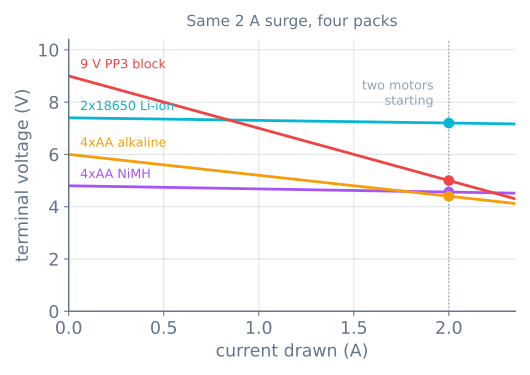
| Pack | Open circuit | R_internal | At a 2 A surge |
|---|---|---|---|
| 2×18650 Li-ion | 7.4 V | ≈ 0.10 Ω | 7.20 V |
| 4×AA NiMH | 4.8 V | ≈ 0.12 Ω | 4.56 V |
| 4×AA alkaline | 6.0 V | ≈ 0.80 Ω | 4.40 V |
| 9 V PP3 block | 9.0 V | ≈ 2.0 Ω | 5.00 V, and falling |
Three things follow that are worth more than the numbers:
The nine-volt block is the worst battery you can put in a robot. It has the highest voltage printed on it and about 500 mAh of capacity behind two ohms of internal resistance. It is a battery for a smoke alarm.
Alkaline cells are not stiff. Their internal resistance is roughly six times a NiMH cell’s, and it rises as they discharge — so the robot works for twenty minutes and then starts resetting, which reads like an intermittent fault and is just a flat battery behaving exactly as it should.
Rechargeables win on the thing that matters. NiMH and Li-ion are the standard robot chemistries not because they are rechargeable but because they hold their voltage under load.
Budget the current before you choose the pack
Add up what the robot draws, twice — once for what it normally uses, and once for the worst instant.
| Part | Running | Worst case |
|---|---|---|
| Arduino Uno board | 45 mA | 45 mA |
| TT gearmotor ×2 | 400 mA | 2000 mA (both stalled) |
| IR reflectance array | 100 mA | 100 mA |
| HC-SR04 | 15 mA | 15 mA |
| SG90 servo | 150 mA | 700 mA (stalled) |
| HC-05 Bluetooth | 30 mA | 40 mA |
| ESP32 (Wi-Fi) | 80 mA | 250 mA (transmit burst) |
A plain line follower — Uno, two motors, an IR array — is about 545 mA running and 2.15 A at the worst instant. The worst instant is normally brief; the exception is a robot pushing at its traction limit, which sits at stall current for as long as the push lasts. Size the pack on the first number and the sag on the second, because they answer different questions:
runtime  ≈ capacity / running current      2000 mAh / 545 mA ≈ 3.7 h ideal
sag      = worst-case current × R_internal
Expect real runtime around two thirds of that figure. You will not drain a pack to zero, the surges cost more than their average, and capacity ratings are measured at gentle discharge rates.
The gap the brown-out detector misses
Every AVR has a brown-out detector that holds the chip in reset below a set voltage. On an Arduino Uno that fuse ships at 2.7 V.
An ATmega328P at 16 MHz is not rated to run at 2.7 V. Its datasheet speed grade runs from 4 MHz at 1.8 V up to 20 MHz at 4.5 V, and interpolating to 16 MHz gives a minimum of about 3.8 V.
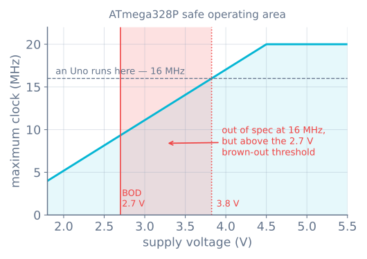
This explains the symptom people find hardest to believe: a robot that does not cleanly reset but simply behaves oddly when the motors run. Corrupted variables, a servo that jumps, an I²C sensor returning nonsense, a state machine in a state it has no transition into. In that band the chip is executing instructions outside its guaranteed operating conditions, and “guaranteed” is exactly the word doing the work.
So do not treat “it did not reset” as evidence the power is fine.
One pack, two rails
The fix is not two batteries. It is one pack feeding two paths.
- Motor current goes from the pack straight into the driver’s motor supply terminal — an L298N’s
+12V, a TB6612FNG’sVM. It never passes through the microcontroller. - Logic current comes from a regulated 5 V — the driver’s onboard regulator, a separate buck module, or USB while you are developing.
- The grounds must be tied together. Every signal between the board and the driver is a voltage measured against ground; with no shared reference, the direction pins mean nothing. This is the second most common wiring fault after the first one.
Never run motors through an Arduino’s 5 V pin or its barrel-jack regulator. The Uno’s regulator is a small linear part that burns the difference between input and output as heat: at 7.4 V in, 5 V out and 500 mA, that is (7.4 − 5) × 0.5 = 1.2 W in a package with no heatsink. It will get hot, then it will shut down thermally, and the robot will reset for a reason that has nothing to do with the battery.
What a capacitor actually fixes
The standard advice is to put a big electrolytic across the motor supply. That advice is right, and the reason usually given for it is wrong, and the arithmetic settles it:
ΔV = I × Δt / CA 1000 µF cap asked to carry a 2 A startup surge lasting 10 ms would drop 2 × 0.010 / 0.001 = 20 V. It cannot do that job. A capacitor does not carry the motor startup surge — only a stiffer battery does.
What it does carry is the fast stuff. At an 8 kHz PWM switching frequency the period is 125 µs, so the same cap sees 2 × 0.000125 / 0.001 = 0.25 V of ripple — a job it does comfortably. It also absorbs the commutation spikes brushed motors throw back down the supply.
So fit one — 470 to 1000 µF across the motor supply, plus a 0.1 µF ceramic close to the driver — and expect it to clean up noise and misbehaving sensors. Expect it not to fix a reset. If a capacitor cured your reset, the pack was borderline and you have bought yourself very little margin.
Measure it rather than guessing
Ten minutes with a multimeter beats an afternoon of theories.
- Set the meter to DC volts and put it across the battery terminals, not across the Arduino.
- Note the resting voltage.
- Start the motors, ideally under real load with the robot on the floor.
- Watch the number.
A drop of more than a few tenths of a volt is your answer. To get R_internal from that, divide: a 6.0 V pack falling to 4.4 V while drawing about 2 A gives (6.0 − 4.4) / 2 = 0.8 Ω.
Then repeat the measurement on the 5 V rail while the motors start. That is the number the microcontroller actually experiences, and if it dips towards 3.8 V you have found the fault without needing a scope.
Cheap meters average too slowly to catch the very bottom of a millisecond dip, so treat what you read as optimistic. The dip is at least that bad.
Fixes, cheapest first
- Stop powering motors through the board. Free, and it fixes a large fraction of cases outright.
- Change the pack. Alkaline or 9 V → NiMH or 18650. Usually the whole fix.
- Tie the grounds together. Free, and its absence causes stranger faults than a brown-out.
- Add the bulk capacitor. For noise and sensor glitches, not for resets.
- Ramp the motors instead of stepping them. A motion profile spreads the startup current over time rather than demanding all of it in one instant — the same code that stops the wheels slipping.
- Size the motors properly. If a motor is being asked for more torque than it should be, it is drawing more current than it should be; the gearmotor sizing arithmetic is upstream of this whole problem.
- Separate the regulator. A small buck converter for the logic rail decouples it from motor sag entirely.
Once the rail is sorted, measuring it in software is the next step — and reading a voltage honestly is harder than it looks, because the ADC’s default reference is the rail.
When it goes wrong
| Symptom | Usually |
|---|---|
| Serial output restarts from the top when motors start | Brown-out; check the pack before the code |
| Works on USB, fails on battery | The pack cannot supply the surge, USB can |
| Works for twenty minutes, then resets repeatedly | Alkaline internal resistance rising as it discharges |
| Odd behaviour but no clean reset | Supply in the 2.7–3.8 V band; out of spec, below no threshold |
| Sensors return nonsense only while driving | Supply noise; bulk capacitor and separate rails |
| Direction pins seem to do nothing | No common ground between board and driver |
| Regulator too hot to touch | Logic drawn through a linear regulator with too much input voltage |
| A capacitor fixed it, then it came back | Pack was marginal; the cap bought milliseconds, not amps |
Power is the layer underneath every other layer of a robot, which is why a fault here imitates a fault anywhere else. When something inexplicable starts happening the moment the motors run, measure the battery first — it costs ten minutes and it is right more often than any other guess.
Explore the graph
Part of these builds
Projects and learning paths that include this tutorial.
- ProjectBuild a GPS Waypoint Rover That Drives Itself
- ProjectBuild a Mecanum Robot That Drives Sideways
- ProjectBuild a Mini Sumo Robot: Grip, Wedge and Edge Sense
- ProjectBuild a Pen Plotter: Two Stepper Axes That Arrive
- ProjectBuild a Pick-and-Place Robot That Knows It Missed
- ProjectBuild a Room Coverage Robot That Sweeps a Floor
- Learning pathHolonomic Drive: Move Sideways Without Turning
- Learning pathPrecision Motion With Steppers: A Learning Roadmap
- Learning pathRobot Electronics Foundations: A Learning Roadmap
Further reading