
Component · Driver
A4988 Stepper Driver
The cheap carrier board that regulates current into a stepper coil. How to set the limit with a meter, the sense resistor trap, and when to reach for a TMC.
What it is
An A4988 carrier is a postage-stamp board that sits between a microcontroller and a bipolar stepper motor. You give it two signals — a pulse and a direction — and it handles everything else: energising the coils in the right sequence, and, crucially, regulating how much current goes into them.
That second job is the one that matters and the one people skip. A stepper winding is a low-resistance inductor, typically 2 to 4 ohms. Connect 24 V across 2.8 Ω and Ohm’s law gives 8.6 A, which will destroy a 1.7 A motor in seconds. The A4988 avoids that by chopping the supply on and off tens of thousands of times a second, holding the average current at whatever you set.
So the board has exactly one adjustment: a trim pot that sets the current limit. Get it right and the driver is invisible. Get it wrong and you have either a weak motor that loses steps or a hot one that cooks.
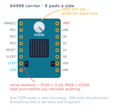
Pinout
| Pin | Direction | What it does |
|---|---|---|
| VMOT | Power in | 8–35 V motor supply. Needs 100 µF across it, close by. |
| GND (motor side) | Power | High-current return |
| VDD | Power in | 3–5.5 V logic supply, a few mA |
| GND (logic side) | Power | Must share ground with the motor supply |
| 1A, 1B | Out | One motor coil |
| 2A, 2B | Out | The other motor coil |
| STEP | In | One rising edge = one microstep |
| DIR | In | High or low picks the direction |
| ENABLE | In | Active low. Tie to ground to energise. |
| RESET | In | Must be high. Jumper it to SLEEP. |
| SLEEP | In | Must be high for the driver to run |
| MS1, MS2, MS3 | In | Microstep resolution; pulled down internally |
Two pins account for most “it does nothing” reports: ENABLE left floating or high (it is active low, so it must be pulled down), and RESET left floating (it must be high, which is why every wiring guide tells you to jumper RESET to SLEEP).
Wiring to an Arduino
Arduino 5V  ──── VDD
Arduino GND ──── GND (logic)  ──┬── GND (motor)
                                └── PSU −
PSU + (12–24 V) ──── VMOT ──┬── 100 µF electrolytic ──┘

Pin 3  ──── STEP            RESET ──┬── SLEEP
Pin 4  ──── DIR
Pin 5  ──── ENABLE          MS1, MS2, MS3 ──── 5 V  (1/16 stepping)

Motor coil A ──── 1A, 1B
Motor coil B ──── 2A, 2B
Non-negotiables:
- 100 µF electrolytic across VMOT and GND, physically close to the board. This is the single most common cause of a board that dies on power-up.
- Common ground between the Arduino and the motor supply. Without it the STEP signal has no reference and the driver sees noise.
- Never unplug the motor while powered. An interrupted energised coil produces a spike with nowhere to go.
- Coil pairing matters; polarity within a pair does not. If the motor buzzes without turning, the pairs are wrong. If it turns the wrong way, swap two wires of one pair.
Setting the current limit — the numbers
Vref = I_phase × R_sense × 8Measure Vref between the trim pot’s metal screw and a ground pin, with VMOT powered and the motor disconnected. Aim for 70–85% of the motor’s rated current: the last fifth buys very little torque and a lot of heat.
| Target current | R_sense = 0.1 Ω (R100) |
R_sense = 0.05 Ω (R050) |
|---|---|---|
| 0.6 A | 0.48 V | 0.24 V |
| 1.0 A | 0.80 V | 0.40 V |
| 1.2 A | 0.96 V | 0.48 V |
| 1.5 A | 1.20 V | 0.60 V |
| 1.7 A | 1.36 V | 0.68 V |
Read the marking on the two black SMD resistors near the bottom edge before you calculate. Setting 1.2 V on an R050 board asks for 3 A through a motor rated for 1.7 A.
Use a ceramic screwdriver. A metal one that bridges the pot to something else on a live board is a routine way to destroy a driver.
What you are setting, physically, is the peak torque the motor can produce — the T_peak in the sine law that governs everything a stepper does. Too low and the rotor lags further behind for the same load and slips sooner; too high and you get heat you did not need.
Microstepping
| MS1 | MS2 | MS3 | Resolution | Steps/rev |
|---|---|---|---|---|
| low | low | low | Full step | 200 |
| high | low | low | Half | 400 |
| low | high | low | Quarter | 800 |
| high | high | low | Eighth | 1600 |
| high | high | high | Sixteenth | 3200 |
All three high is the normal choice. It is worth being clear about why: microstepping does not make the machine more accurate under load — the error a load causes is unchanged by how finely you divide the step. What it does is stop the rotor ringing at every step, which is the difference between a machine that screams and one that hums, and between a surface with visible step ripple and one without.
The cost is pulse rate. At 1/16 on an 80 steps/mm axis, 100 mm/s needs 8 000 pulses per second. An Arduino Uno bit-banging steps runs out somewhere around 10 000–15 000 per second, which is a real ceiling on a lead-screw axis at 400 steps/mm.
Current, heat and the power budget
The A4988’s own dissipation is modest — the pain is thermal density, not total watts. Roughly 0.5 W per phase at 1 A in a package with almost no copper to spread it into. The limits in practice:
| Cooling | Safe continuous current |
|---|---|
| Bare chip, still air | ~1.0 A |
| Stick-on heatsink | ~1.2 A |
| Heatsink plus moving air | ~1.5 A |
| Anything above that | Use a DRV8825 or a TMC2209 |
Thermal shutdown does not announce itself. The driver stops, the motor stops mid-move, the driver cools and restarts, and what you observe is an axis that “randomly” loses a chunk of position. An axis that fails more often late in a long job, or in a warm room, is thermal until proven otherwise.
On the supply side, remember the chopper behaves as a buck converter: the current drawn from a 24 V supply is well below the phase current, so budget on power rather than adding up phase currents. Each motor at a 1.2 A limit on 2.8 Ω windings dissipates about 8 W, and it does that whenever it is energised — including standing still. See the robot power budget.
Minimal working code
const int STEP_PIN = 3, DIR_PIN = 4, EN_PIN = 5;

void setup() {
  pinMode(STEP_PIN, OUTPUT);
  pinMode(DIR_PIN, OUTPUT);
  pinMode(EN_PIN, OUTPUT);
  digitalWrite(EN_PIN, LOW);        // active low — energise the coils
  digitalWrite(DIR_PIN, HIGH);
}

void loop() {
  for (int i = 0; i < 3200; i++) {  // one revolution at 1/16
    digitalWrite(STEP_PIN, HIGH);
    delayMicroseconds(2);           // datasheet minimum is 1 us
    digitalWrite(STEP_PIN, LOW);
    delayMicroseconds(300);         // this delay is the speed
  }
  delay(1000);
}
Good for a bench test, wrong for a machine: the step rate jumps straight to full, which above the motor’s pull-in rate produces a buzz and no motion. Use AccelStepper or your own motion profile for anything that has to arrive somewhere. You can watch exactly what that unramped command does to the rotor in the stepper simulator.
What current to actually set
The rated current on a motor’s label assumes the cooling conditions of a test rig — bolted to a large aluminium plate, in still air at 25 °C. Your machine is a printed bracket in a warm room.
A working rule, with the reasoning rather than just the number:
| Situation | Set the limit at | Why |
|---|---|---|
| Plenty of torque margin, quiet wanted | 60–70% of rated | Torque falls linearly, heat falls as the square |
| Normal machine | 70–85% of rated | The usual answer |
| Genuinely torque-limited | 90–100% of rated | Only with a heatsink and airflow |
| Above rated | Never | You are not buying torque, only heat |
The reason the low end costs less than it looks is in the second column. Torque is proportional to current, but heat is proportional to current squared. Dropping from 1.7 A to 1.2 A gives up 29% of the torque and removes half the heat:
1.7 A: P = 2 × 1.7² × 2.8 = 16.2 W per motor
1.2 A: P = 2 × 1.2² × 2.8 =  8.1 W per motor
If the sizing arithmetic says you are using 12% of the available torque, the 29% you gave up was never doing anything.
De-energising, and the pin most builds ignore
ENABLE exists because a stepper burns its full set current standing perfectly still. That is unlike every other motor a beginner has met, and it has consequences:
// Two energised NEMA 17s at 1.2 A dissipate ~16 W doing nothing at all.
digitalWrite(EN_PIN, HIGH);   // active low, so HIGH = coils off
When to use it:
- Between jobs on X and Y. A plotter or laser gantry has no reason to hold position while idle, and 16 W of heat into a printed frame over an hour is enough to matter.
- Never on a Z axis holding weight, unless the mechanism is self-locking. A T8 lead screw will not backdrive, so de-energising is safe. A belt-driven Z will drop the moment you cut the current.
- Never mid-move. The rotor keeps going, the field does not, and you have thrown away the position with no way to know by how much. Stop, then disable.
The catch that surprises people: after de-energising, the rotor settles onto the nearest detent — the magnetic rest position it has with no current at all — which may be up to a full step away from where it was being held. On a belt axis at 80 steps/mm that is 0.2 mm of unannounced movement, so either re-home after every disable, or accept that idle-disable and sub-tenth accuracy do not go together.
SLEEP is the deeper version: it shuts down the internal regulator too, drawing microamps instead of milliamps, but it needs about 1 ms to wake and it resets the driver’s internal step position to the home microstep. That last part is the trap — waking from SLEEP can shift the motor by up to a full step. For almost every hobby machine, ENABLE is the pin you want and SLEEP is the pin you jumper high and forget.
Troubleshooting
| Symptom | Cause | Fix |
|---|---|---|
| Nothing happens at all | ENABLE high, or RESET floating | Tie ENABLE low; jumper RESET to SLEEP |
| Motor vibrates, does not rotate | Coil pairs wired across each other | Re-pair with a meter on ohms |
| Board died on power-up | No bulk capacitor on VMOT | 100 µF electrolytic, close to the pins |
| Stops mid-move, restarts later | Thermal shutdown | Lower Vref; add heatsink and airflow |
| Weak, skips under light load | Vref too low | Re-measure; check the sense resistor marking |
| Motor screaming hot | Vref too high | Recalculate — did you use the right R_sense? |
| Missing steps only at high speed | Supply voltage too low | Raise VMOT; current will not help |
| Missing steps only on acceleration | Ramp too aggressive | Lower acceleration, or raise Vref |
| Loud at every step | Full stepping — MS pins floating | Tie MS1–MS3 high |
| Works on the bench, fails in the frame | Endstop or STEP lead picking up noise | Route signal leads away from motor cables |
A4988, or the alternatives?
| Driver | Current | Microstep | Noise | Choose it when |
|---|---|---|---|---|
| A4988 | 1 A / 1.5 A cooled | 1/16 | Audible | Cheap, ubiquitous, well documented |
| DRV8825 | 1.5 A / 2.2 A cooled | 1/32 | Audible | You need more current or finer steps |
| TMC2208 | ~1.2 A | 1/256 | Near silent | Noise matters |
| TMC2209 | ~1.7 A | 1/256 | Near silent | Noise matters, plus sensorless homing |
| L298N | 2 A | — | — | DC motors. No current regulation. |
| TB6612FNG | 1.2 A | — | — | DC motors, efficiently |
The L298N and TB6612FNG rows are there because both datasheets mention steppers, and both will technically turn one. Neither regulates current, so you get a fraction of the torque and a lot of waste heat. They are DC motor drivers; use them for driving wheels.
The TMC drivers are worth the extra money the moment the machine lives somewhere you can hear it. Same job, smoother current waveform, and a printer fitted with them makes fan noise instead of motor noise.
Where it is used
This driver powers both axes of the pen plotter build, and setting it up correctly is a checkpoint on the precision motion roadmap. The full wiring and Vref walkthrough covers the procedure step by step.
Explore the graph
Used in these builds
Projects, learning paths, and simulators that include the A4988 Stepper Driver.
Compare
Alternatives
Questions
A4988 Stepper Driver FAQ
How do I calculate Vref for an A4988?
Vref equals the phase current you want, times the sense resistor value, times eight. For a 1.2 A target on a board with 0.1 ohm resistors that is 1.2 × 0.1 × 8 = 0.96 V, measured between the trim pot's wiper and ground with the board powered on VMOT and the motor disconnected. The critical detail is the sense resistor: carriers ship with either 0.1 ohm marked R100 or 0.05 ohm marked R050, and using the wrong one puts exactly double the current through your motor.
Why is my A4988 getting so hot that it cuts out?
Almost always the current limit is set too high. A bare A4988 handles about 1 A continuously; with a heatsink and moving air it manages around 1.5 A. Above that its thermal shutdown trips, the motor stops mid-move, and then it restarts once it cools — which looks like random step loss. Re-measure Vref against the sense resistor you actually have, stick the heatsink on, and point a fan at it. If you genuinely need more than 1.5 A, the A4988 is the wrong part.
What is the difference between an A4988 and a DRV8825?
The DRV8825 handles more current (about 1.5 A bare, 2.2 A cooled), goes to 1/32 microstepping instead of 1/16, and takes a higher motor voltage at 45 V. It is pin compatible, so it drops into the same socket — but its Vref formula is different, Vref equals current times 0.5, and its trim pot turns the opposite way. Swapping one in without re-reading the formula is a common way to cook a motor.
Do I really need the capacitor across VMOT?
Yes. A 100 µF electrolytic between VMOT and ground, physically close to the board, is required rather than recommended. The chopper draws current in sharp bursts, and without bulk capacitance nearby the inductance of your supply leads turns those bursts into voltage spikes that exceed the chip's 35 V limit. Boards that die the instant they are powered up have usually died of this.
What do MS1, MS2 and MS3 do if I leave them unconnected?
They have internal pull-downs, so leaving them floating selects full stepping — 200 steps per revolution and a motor that rings audibly at every step. Tie all three high for 1/16 stepping, which is what most builds use. It does not make the machine more accurate under load, but it stops the ringing, which makes it quieter and improves surface finish. The cost is sixteen times as many pulses per millimetre for your microcontroller to issue.
Can an A4988 drive a DC motor or a servo?
No. It is a bipolar stepper driver: it expects two coils and drives them with a specific current sequence. A DC motor needs an H-bridge like the L298N or TB6612FNG; a hobby servo needs a 50 Hz PWM signal and no driver at all. The A4988's STEP and DIR interface has no meaning for either.
Further reading