
Component · Chassis
Mecanum Wheel Set
The wheel that pushes at 45°. Which of the four is left-handed, the X check that catches a backwards fit, and the traction you trade for sideways motion.
What it is
A mecanum wheel is an ordinary wheel with a ring of free-spinning rollers bolted round its rim, each roller’s axle set at 45° to the wheel’s own. Bengt Ilon patented it in 1972 at the Swedish company Mecanum AB, which is where the name comes from, and warehouse robots have been quietly using it ever since.
The consequence of that 45° is the whole story. A normal wheel can push only along the direction it rolls. A mecanum wheel can push only along its roller’s axle — because the roller spins freely in every other direction and simply refuses to transmit force there. So one mecanum wheel’s ground force is pinned at 45° to the chassis, permanently, whatever the motor does.
One such wheel is useless. Four of them, in two left-handed and two right-handed pairs, give you four force vectors at alternating 45° angles, and the sum of four vectors can point anywhere on the floor and carry a twist. That is a holonomic base: three controllable degrees of freedom — forward, sideways, rotation — from four ordinary, un-steered motors.
Handedness, and why it is not optional
Mecanum wheels come in two mirror-image forms, usually sold as left (A) and right (B), or just marked L and R on the hub. A robot needs two of each, diagonally paired:
| Corner | Handedness | Its force vector, seen from above |
|---|---|---|
| Front left | Left-handed (A) | Points forward-right when the wheel drives forward |
| Front right | Right-handed (B) | Points forward-left |
| Rear left | Right-handed (B) | Points forward-left |
| Rear right | Left-handed (A) | Points forward-right |
Diagonal corners share a hand. Buying four of the same wheel is a real and common mistake — a “set of four mecanum wheels” from a reputable seller contains two of each, but two singles ordered separately very often do not.
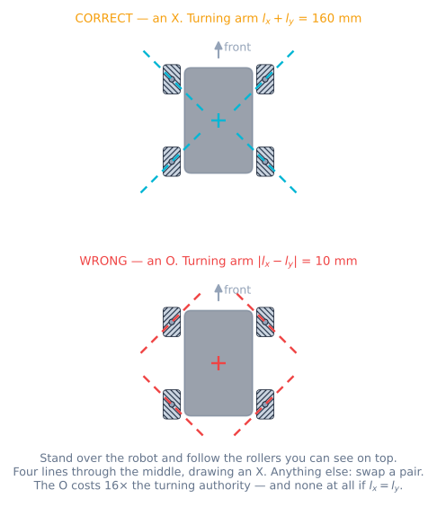
The X check
The reliable test needs no markings at all.
- Put the robot on the bench, wheels down.
- Stand over it and look straight down.
- On each wheel, follow the line of the rollers you can see on top.
- Those four lines should aim at the middle of the robot and draw an X.
If they draw a diamond — the O or rhombus configuration — swap two wheels diagonally and check again.
One subtlety that trips people up when they try to reason it out instead of looking: the rollers you see on top are mirrored from the ones touching the floor, because a roller at the top of the wheel is the same roller carried half a turn round. The rollers doing the pushing point the other way. It does not matter — the X you can see is still the right test, and it is the one everyone uses, precisely because you can see it.
Wiring four of them to an Arduino
Mecanum is a four-motor drivetrain, so a single L298N is not enough. Two dual H-bridges, or one four-channel board:
| Wheel | Driver | Direction pins | PWM pin | Encoder A/B |
|---|---|---|---|---|
| Front left | Driver 1, channel A | 2, 4 | 3 | 18, 30 |
| Front right | Driver 1, channel B | 7, 8 | 5 | 19, 31 |
| Rear left | Driver 2, channel A | 24, 26 | 6 | 20, 32 |
| Rear right | Driver 2, channel B | 28, 22 | 11 | 21, 33 |
Two details that bite:
- Four PWM channels that share a timer will not all work. On an Uno there are six PWM pins across three timers, and the Servo library or
tone()will steal one. A Mega or an ESP32 makes this a non-problem; on an Uno, check the timer map before you solder. - Four encoders want four interrupt pins. An Uno has two. This is the single most common reason a mecanum build ends up on a Mega 2560 or an ESP32.
Minimal working code
The inverse kinematics is four lines. Everything else is plumbing.
// Mecanum inverse kinematics: a chassis command in, four wheel speeds out.
// x is forward, y is to the robot's LEFT, omega is counter-clockwise.
const float LX = 0.075;   // half the wheelbase, m
const float LY = 0.085;   // half the track, m
const float K  = LX + LY; // the only place geometry enters

void driveMecanum(float vx, float vy, float omega) {
  float fl = vx - vy - K * omega;
  float fr = vx + vy + K * omega;
  float rl = vx + vy - K * omega;
  float rr = vx - vy + K * omega;

  // Scale, do not clip. Clipping each wheel on its own keeps the speed and
  // throws the direction away, which is a bug you will chase for a week.
  float peak = max(max(fabs(fl), fabs(fr)), max(fabs(rl), fabs(rr)));
  if (peak > V_MAX) {
    float s = V_MAX / peak;
    fl *= s; fr *= s; rl *= s; rr *= s;
  }

  setWheel(FL, fl); setWheel(FR, fr);
  setWheel(RL, rl); setWheel(RR, rr);
}
setWheel() is where the velocity loop lives, if you have one. Open-loop it is just a PWM write, and open-loop mecanum drifts — see closing the loop on wheel velocity.
The numbers that matter
Three of them, and all three are geometry rather than anything you can buy your way out of.
| Quantity | Mecanum | Plain wheels | Why |
|---|---|---|---|
| Straight-line traction | 71% (1/√2) | 100% | Friction caps the whole 45° force vector; only its forward component moves you |
| Acceleration ceiling on μ = 0.85 | 5.9 m/s² | 8.3 m/s² | Same ratio, and the robot’s mass cancels out of both |
| Top diagonal speed | 71% of top wheel speed | n/a | A 45° command asks two wheels for everything and two for nothing |
| Degrees of freedom | 3 | 2 | The thing you bought them for |
That last row is what you are paying for. The first three are the bill.
Troubleshooting
| Symptom | Cause | Fix |
|---|---|---|
| Forward is fine, strafing curves and spins | A wheel in the wrong corner | Do the X check; swap two wheels diagonally |
| Strafes the wrong way | All four wheels mirrored — the X is inside out | Swap left pair with right pair |
| Drifts a little to one side on a long straight | Motors do not match under load | Close the velocity loop per wheel, or match and calibrate |
| Diagonal is much slower than forward | Working as designed, not a fault | The 1/√2 ceiling; raise the top speed or stop using diagonals |
| Robot judders and squeals sideways | Rollers skidding rather than rolling — too much grip, too little load, or a seized roller | Spin each roller by hand; every one should turn freely |
| Odometry good forward, hopeless sideways | The rollers slip by design, so the encoder is not measuring the floor | Add an IMU for heading; add dead wheels for position |
| A corner sounds different from the others | One roller’s bearing has collapsed | Replace the roller; a seized one turns that corner into a 45° plain wheel |
Mecanum, or the alternatives?
| Option | Moves sideways | Pushing power | Terrain | Cost and complexity |
|---|---|---|---|---|
| Mecanum, 4 motors | Yes, any direction, any heading | Poor — 71% before roller rubber | Flat hard floors only | 4 motors, 4 drivers, 4 encoders |
| Omni wheels in X, 4 motors | Yes — same diamond envelope, rotated 45° and √2 taller | Poor, and √2 less force for that speed | Flat floors only | Same motor count, awkward to package |
| Differential drive, 2 motors | No — must turn first | Best on the same wheels | Handles a lot more | 2 motors, cheap, simple, robust |
| Swerve, 8 motors | Yes, with full traction | Excellent | Good | Four times the work and the cost |
The honest summary: a mecanum base is the right answer when the floor is flat and clean, space is tight, and the robot has to hold a heading while moving — a warehouse aisle, a competition field, a camera platform. It is the wrong answer when the robot has to push, climb, or know exactly where it is from wheels alone.
Where it is used
Drop these under a chassis and you are building the mecanum omnidirectional robot. Before you cut any metal, spend twenty minutes in the mecanum drive simulator — fitting a wheel backwards there costs nothing, and it is the failure you are most likely to build.
Explore the graph
Used in these builds
Projects, learning paths, and simulators that include the Mecanum Wheel Set.
Compare
Alternatives
Questions
Mecanum Wheel Set FAQ
How do I know which mecanum wheel goes where?
Put the robot on the bench, stand over it and look straight down. Follow the line of the rollers you can see on the top of each wheel. On a correctly built base those four lines aim at the middle of the robot and together they draw an X. If they draw a diamond — a rhombus, an O — two of your wheels are in the wrong corners. That check takes five seconds, needs no markings, and catches the single most common mecanum build error. Printed L and R stamps on the hub help, but the X check is what you trust, because it tests the thing that actually matters.
What happens if one mecanum wheel is fitted backwards?
The robot still drives, which is what makes it so confusing. Forward and reverse look normal because the sideways components still mostly cancel. It is strafing that goes wrong: the mis-fitted corner pushes across the command instead of into it, so a sideways command comes out as a slow curve with a spin in it. In the simulator, a strafing square that closes to 17 mm with all four wheels right ends up more than a metre away and tens of degrees rotated with one wheel backwards. Nothing in the code is wrong, and no amount of PID tuning will fix it. The tell you can read on a real robot is the encoder residual, which goes from zero to about 0.28 and stays there.
Do mecanum wheels need encoders?
They need them more than a differential-drive robot does, and they get less out of them. More, because the four wheels have to hold their speed ratios for the robot to go where it was pointed, and a motor that droops under load quietly steers you off course. Less, because the rollers slip by design, so a wheel encoder measures the wheel and not the ground — the sideways part of your odometry is the least trustworthy number on the robot. Most serious mecanum builds keep encoders for the velocity loop and add an IMU, or unpowered omni dead wheels, for position.
Why is my mecanum robot so easy to push around?
Because a mecanum wheel can only bite along its roller's axle, which sits at 45 degrees to the direction you want to go. Friction limits the whole force vector, but only the component along the rolling direction moves the robot — so you get 1/√2, about 71%, of the traction the same robot and the same floor would give on plain wheels. Roller rubber is usually grippier than that sounds, but the geometry penalty is real and there is no setting that removes it. If pushing hard is the point, do not use mecanum wheels.
Can I use mecanum wheels on carpet or outdoors?
Carpet works but eats speed and accuracy: the rollers dig in rather than sliding, so sideways motion gets noisy and odometry gets worse. Outdoors is a no. Gravel, grass and anything with a lip will jam a roller or stop it dead, and a jammed roller turns that corner into an ordinary wheel pointing 45 degrees off — which is the backwards-wheel failure again, intermittently. Mecanum wheels are for flat, hard, clean floors, which is exactly where warehouses and competition fields are.
How many motors does a mecanum robot need?
Four, one per wheel, each independently controllable in both directions. There is no such thing as a two-motor mecanum drive — the whole mechanism is four force vectors summing to whatever you asked for, and tying two wheels to one motor removes two of them. That means four H-bridge channels, four sets of encoder wires if you want a velocity loop, and a current budget that is four motors deep rather than two.
Further reading