
Tutorial · Intermediate · 30 min
Gearbox Backlash in Robots: How to Measure and Fix It
The play in every gear train that makes an arm droop and odometry drift. Measure yours in degrees, then choose whether to remove it or design around it.
Introduction
There is a family of robot faults that all present the same way: the machine is fine going one direction and wrong going the other. The arm reaches the same point from the left and from the right and lands two positions apart. The balancing robot judders around upright and will not settle no matter how you tune it. The maze robot’s heading is out by a degree after every turn and by fifteen after the run.
None of those are tuning problems, and all of them have the same cause. Between your motor and the thing it moves is a gear train, and a gear train has to have a gap between its teeth or it would jam. That gap is called backlash, and it means that whenever the motor changes direction the output does not move at all until the teeth cross the gap and meet on the other side.
This site names backlash on seven pages as the reason something does not work. This is the page that explains it.
What it actually is
Backlash is not friction, and it is not a lag. It is a dead zone with memory.
Picture the driving tooth sitting against one face of the driven tooth. Push, and the output tracks the input exactly — no error at all. Now reverse. The driving tooth leaves that face and travels across the gap, and for the entire crossing the output stays exactly where it was. When contact is made on the far face, the output starts tracking again, permanently offset by the width of the gap.
Two consequences fall straight out of that description and they are the ones worth keeping:
- Backlash costs you nothing while you move in one direction. It is a reversal tax, charged once per reversal, no matter how far you then travel. The most expensive reversal a robot makes is an emergency stop, where the play is free travel added straight onto the stopping distance.
- The error depends on which way you came from. That is what makes it a hysteresis rather than a simple offset, and it is why a calibration constant cannot remove it.
The shape it makes
Drive a joint with 4° of play back and forth and plot what the output does.
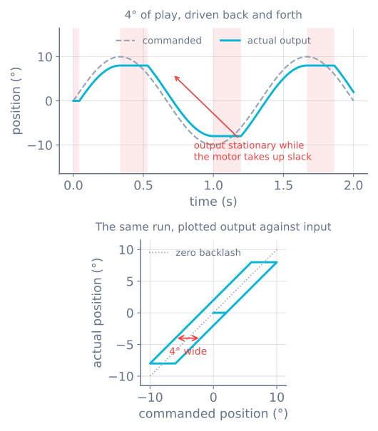
The lower panel is the useful mental image, because it makes the two branches obvious. Going up, the output sits half a gap behind. Coming down, it sits half a gap ahead. Anywhere in between, the output is wherever it was left.
Measure yours in ten minutes
You cannot design around a number you do not have, and every gearbox is different. There are two ways to get it.
By hand, for anything. Power the motor down and hold the chassis still. Stick a strip of tape to the rim of the wheel or the end of the arm and rock the output gently between its two stops — not hard enough to flex anything, just to the point where it meets resistance each way. Mark both extremes and measure the arc between them. Convert:
backlash (°) = arc / (π · D) × 360Repeat at four or five positions around a full output revolution and keep the worst one. Tooth-to-tooth variation and shaft eccentricity are real, and the position you happened to test first is not necessarily representative.
With an encoder, more precisely. If your motor has an encoder on the motor shaft — an N20 encoder motor does — drive it very slowly one way until the output just starts to move, zero the counter, then reverse and count until the output moves again. That count is the gap:
backlash (°) = counts / counts-per-output-rev × 360For an N20 with 7 pulses per channel per motor revolution, decoded ×4, behind a 1:100 gearbox, that is 2800 counts per output revolution — so 31 counts is 4°. Plenty of resolution to measure something you can barely see.
Where the encoder sits decides what you can see
This is the part that surprises people, and it decides whether the number you just measured is a problem you can fix in software.
An encoder on the motor shaft sits before the gearbox. During the crossing it reports the motor turning perfectly happily, because the motor is turning perfectly happily. The wheel is not. Your position estimate says you moved; you did not. Backlash is invisible to a motor-side encoder and lands in your odometry as pure, uncorrected error.
An encoder on the output shaft sits after the gearbox and reports the truth — but that is exactly why it reads zero during the crossing, which is why it is the motor-side encoder you use to measure backlash in the first place. The encoder that cannot compensate for it is the one that can see it.
So the honest summary for a hobby robot: on almost all of them, the encoder is on the motor and backlash is unmeasured error in the position estimate. Everything below is about making that error small or making it not matter.
What it is costing you
Play at a joint is an angle; what it costs is a distance, and the lever decides how much. Same 4° of play, three robots:
| Where | Lever | Cost per reversal |
|---|---|---|
| Robot arm shoulder | 150 mm link | 10.5 mm at the gripper |
| Drive wheel | 65 mm wheel | 2.27 mm of travel |
| Micromouse wheel | 42 mm wheel | 1.47 mm of travel |
The arm row is why articulated arms suffer most at hobby tolerances: the shoulder’s play is multiplied by the entire length of the arm before it reaches the tool. One degree at the shoulder of a 150 mm link is already 2.6 mm at the gripper.
The wheel rows look harmless until you count reversals. A micromouse pivots on the spot at every junction, and a pivot turn reverses one wheel every time. With 42 mm wheels on a 90 mm track, 4° of play is 0.93° of heading error per turn — and heading error is the one thing that does not average out, because every subsequent straight is driven along the wrong bearing. A hundred turns is 147 mm of travel your odometry counted and the robot never made.
A self-balancing robot is the extreme case, because it reverses continuously — hundreds of times a second, in small increments, and every increment is smaller than the gap. It spends most of its life inside the dead zone, which is why no set of gains ever settles it.
Fix 1: buy less of it
The cheapest fix is usually the part.
Metal gears instead of plastic. Injection-moulded gears have loose tolerances and wear looser. A metal gear train does not remove backlash but typically has a fraction of it, which is the single reason N20 motors show up in every balancing robot and micromouse build, and why the TT gearmotor is fine for a line follower that mostly drives forwards.
Know which stage matters. Backlash from each stage, referred to the output, is divided by the gear ratio between that stage and the output. The final stage has a ratio of one to the output, so its full backlash appears and everything upstream is divided down. A high-ratio gearbox is therefore not automatically worse — and if you are going to improve one gear, improve the last one.
Preload. Split gears sprung against each other, anti-backlash leadscrew nuts, a tensioned belt instead of a gear pair. All of these hold the teeth in contact on both faces at once. All of them cost friction, efficiency and wear, which is the trade you are making.
Or delete the gearbox. A belt-driven or direct-drive joint has no gear backlash to have. It has compliance instead, which is a different problem covered below.
Fix 2: approach from one side
The oldest fix in machining and the best value in software, because it costs nothing.
Backlash is only charged at a reversal. So arrange for the last part of every move to be in the same direction, and the gap is always already crossed when you arrive. If you need to reach a position from above, overshoot past it and come back up. 3D printers do this on the Z axis; CNC operators do it by hand as a reflex.
// Always arrive travelling positive: the gap is crossed before we get there.
void moveTo(float target) {
  if (target < currentPosition()) {
    driveTo(target - APPROACH_MARGIN);   // margin > measured backlash
  }
  driveTo(target);
}
APPROACH_MARGIN must be comfortably larger than the play you measured — twice it is a reasonable starting point. The cost is time on half your moves, and the benefit is repeatability that no longer depends on where you came from.
For a mobile robot the same trick reads differently: prefer a wide arc to a pivot turn where the map allows one, because an arc never reverses either wheel.
Fix 3: stop the controller fighting it
A PID loop meets backlash as a dead zone in the middle of its own control range, and it handles it badly in a specific, recognisable way.
Inside the gap, output rises and nothing happens, so the error does not shrink. The integral term keeps accumulating through a period when no amount of effort would have helped. When the teeth finally engage, the accumulated term is applied all at once to a mechanism that is now connected, and the joint lurches past the target. Then it reverses, crosses the gap again, and does the same thing in the other direction. That is a limit cycle — a steady hunting oscillation that never converges — and its amplitude is set by the mechanics, not the gains.
What actually helps:
- Stop integrating when you are not moving but you are commanding. If output is above the threshold that should produce motion and the encoder says the output is not moving, freeze the integral. This is the same anti-windup logic you would use against a saturated actuator; the dead zone is just an actuator that is temporarily disconnected.
- Lower
Kibefore you lowerKp. The integral term is the one that turns a dead zone into a limit cycle. - Do not chase the last fraction of a degree. If your play is 4°, a tolerance band of 1° is asking for oscillation. Accept a dead band slightly wider than the backlash and the loop stops hunting.
- Profile the reversal. A motion profile that eases through zero velocity crosses the gap gently instead of slamming into the far tooth face — quieter, and much easier on plastic gears.
Watch this happen in the PID simulator by tuning against a plant that responds sluggishly to small inputs: the same gains that are stable for large moves hunt around the setpoint for small ones.
Compliance is the other half of lost motion
If you measure play by rocking the output, you are measuring backlash and compliance together, and they need different fixes. Tell them apart with one test: apply a load, note the deflection, then release it.
| Backlash | Compliance | |
|---|---|---|
| Deflection vs load | Fixed gap, load-independent | Proportional to load |
| On release | Stays where you left it | Springs back |
| Fix | Better gears, preload, one-sided approach | Stiffer parts, shorter levers, bracing |
| Symptom | Direction-dependent error | Sag under load, ringing after moves |
A long acrylic arm has very little backlash and a great deal of compliance. A cheap plastic gearbox on a short stub shaft is the reverse. Both read as “the arm does not go where I told it”, which is why the two-minute test is worth doing before you buy anything.
When it goes wrong
| Symptom | Usually |
|---|---|
| Arm reaches a point differently from each side | Backlash, straightforwardly — measure it before tuning anything |
| Balancing robot judders and never settles | Play larger than the correction increments; metal gearbox, not more tuning |
| Heading drifts a degree per turn | Backlash on the reversing wheel; prefer arcs, or add a gyro |
| Odometry says it moved and it did not | Motor-side encoder cannot see the gearbox gap |
| Steady oscillation around the setpoint | Integral term winding up through the dead zone |
| Position is repeatable but sags under load | Compliance, not backlash — stiffen, do not re-gear |
| Got worse over a few months | Plastic gear wear; backlash grows with use |
Backlash is the reason a robot that is perfect in simulation is disappointing on the bench, because it is exactly the kind of thing an ideal model leaves out. Measure it once, write the number down, and most of the mystery goes with it. If the number comes out large enough to hurt, the answer is usually a better motor and gearbox rather than another afternoon of tuning.
Explore the graph
Part of these builds
Projects and learning paths that include this tutorial.
Further reading