
Tutorial · Intermediate · 25 min
Robot Arm Types: Cartesian, SCARA, Delta and 6-Axis
Compare the four robot arm architectures by workspace, stiffness, speed and how hard the maths is — and why serial and parallel arms swap the easy direction.
Introduction
The two-link arm is one architecture out of several, and the choice between them is made before any code exists. It fixes the shape of the reachable space, how stiff the machine is, how fast it can move, and how hard the kinematics are to solve.
Pick wrong and no amount of tuning recovers it. A 6-axis arm asked to do flat pick-and-place all day is slower and floppier than the SCARA that costs less; a gantry asked to reach into a box at an angle simply cannot.
The split that matters: serial or parallel
Everything else is detail next to this one.
A serial arm is a single chain. Each joint carries every joint beyond it, plus the payload. That gives a large workspace for the volume the machine occupies, and it means the shoulder motor is lifting the elbow motor, the wrist motor and the tool — so stiffness and payload fall off the further out you go.
A parallel arm drives one platform through several chains at once. Load is shared, the actuators can sit on the fixed base, and the moving structure can be almost nothing. That buys enormous stiffness and speed, and costs workspace: parallel machines reach a fraction of the volume they occupy.
The four you will actually meet
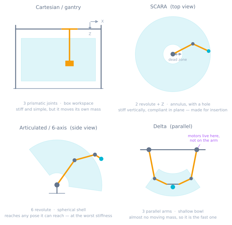
Cartesian / gantry. Three prismatic axes at right angles. The kinematics are trivial because the joint values are the coordinates — no trigonometry anywhere. Rigid, accurate, cheap to make precise. The costs are footprint and mass: the frame must be bigger than the workspace, and every move drags a gantry beam around. Your 3D printer is one.
SCARA. Two revolute joints turning in a horizontal plane, a vertical prismatic axis, and a rotating wrist. The name is the design brief: Selective Compliance — stiff along Z, deliberately compliant in the horizontal plane, so a part being pressed into a hole can shift sideways to find it instead of jamming or breaking. Very fast in plane, and the workspace is an annulus with a dead zone at the middle where the arm cannot fold tightly enough.
Articulated / 6-axis. Six revolute joints. The only one of the four that can put the tool at an arbitrary position and orientation throughout its range, which is why it dominates welding, painting and general-purpose work. It pays for that with the worst stiffness-to-reach ratio and the hardest kinematics.
Delta. Three arms from a fixed base plate to a small moving platform, with parallelogram linkages that keep the platform level. All three motors bolt to the frame, so the moving mass is a few carbon rods and the platform — which is why industrial deltas manage well over a hundred picks a minute. The workspace is a shallow bowl underneath, and the classic form gives you translation only.
Worth knowing about but rarer: the Stewart platform, six prismatic legs to one platform, giving full six-axis motion with extraordinary stiffness over a tiny range. Flight simulators and machine tools.
Forward and inverse swap difficulty
This is the part that catches people out, and it is a genuine symmetry rather than a coincidence.
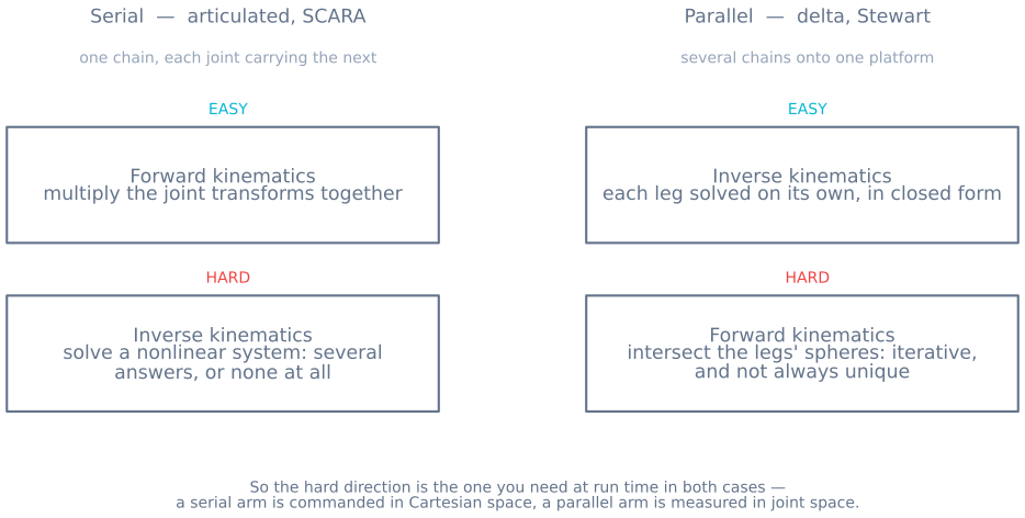
For a serial arm, forward kinematics — joint angles to tool pose — is a chain of matrix multiplications. It always works, it is fast, and there is exactly one answer. Inverse kinematics is the hard direction: a nonlinear system with multiple solutions (elbow-up and elbow-down, and more of them once you have six joints) or none at all.
For a parallel arm it is the other way round. Given a platform pose, each leg is solved independently by simple geometry — closed form, one answer per leg. But going from measured leg lengths back to platform pose means intersecting several spheres simultaneously, which needs an iterative solver and does not always have a unique answer.
The sting is that in both cases the hard direction is the one you need at run time, because you command a machine in Cartesian space and you measure it in joint space. Serial arms therefore ship with a closed-form IK solution wherever possible — the reason most industrial 6-axis arms put three wrist axes through a single point is that this geometry makes an exact solution exist at all. Delta controllers, conversely, run inverse kinematics happily in a loop and only reach for the iterative forward solution during calibration.
The workspace is not the number on the datasheet
“Reach: 900 mm” describes a radius, and almost none of that sphere is usable.
There is an inner limit where the arm cannot fold up tightly enough. There is a floor. There are joint limits that cut whole sectors away. And — the one that surprises people — the reachable volume shrinks dramatically once you require a specific tool orientation, because reaching a point while holding the gripper vertical is a much stronger constraint than reaching it at all.
Two habits fix this before it costs you a rebuild:
- Model the dexterous workspace, not the reachable one: the set of points you can reach at the orientation the job actually needs.
- Check the corners of your task, not its centre. Machines are chosen on the easy pose and defeated by the awkward one.
The robot arm simulator shows the two-link version of this directly — drag a target to the boundary and watch solutions disappear.
Singularities are architecture-specific
A singularity is a configuration where the arm loses the ability to move in some direction, and where the joint speed needed for a modest tool speed goes to infinity.
Serial arms have them at the workspace boundary — fully extended, unable to move further out — and in the interior, most famously the wrist singularity where two wrist axes line up and a degree of freedom vanishes. The symptom is a wrist that suddenly whips through half a turn while the tool barely moves.
Parallel arms have a nastier variety. As well as losing freedom, they can gain an uncontrollable one, in the middle of the workspace, where the platform becomes locally free to move with the actuators locked. That is a stiffness failure rather than a speed one, and you can drive into it during ordinary work rather than only at the edges.
Choosing one
| If the job is | Take | Because |
|---|---|---|
| Flat layered work in a box — printing, routing, plotting | Cartesian | Trivial kinematics, high stiffness, accuracy is cheap |
| Fast pick-and-place between two heights | SCARA | Quick in plane, and the compliance is designed for insertion |
| Anything needing arbitrary tool angles | Articulated | The only one with genuine six-axis freedom |
| Very high rate, light parts, shallow volume | Delta | Motors on the frame means almost no moving mass |
| Tiny range, huge stiffness, six axes | Stewart platform | Load shared across six legs |
Speed and stiffness track moving mass, which tracks where you put the motors. That single idea explains most of the table.
What this changes for a hobby build
Nearly every hobby arm is articulated, because servo brackets make it the easiest thing to bolt together — and it is also the architecture that suffers most at hobby tolerances. Backlash at the shoulder is multiplied by the whole length of the arm by the time it reaches the gripper — 4° at a joint driving a 150 mm link is 10.5 mm at the tool.
Three things follow:
- Put the heavy things low. A servo at the wrist is a mass the shoulder accelerates through the longest lever you have.
- Profile the moves. A step command at the base becomes a visible wobble at the tool, because the arm is a spring with a mass on the end. Motion profiles fix more arm wobble than stiffer brackets do.
- Consider not building an articulated arm. If the task is flat, a gantry made from two linear rails will beat a servo arm on accuracy for less money — and you already know how to write its kinematics.
When it goes wrong
| Symptom | Usually |
|---|---|
| Arm reaches the test point but not the real one | Dexterous workspace is smaller than the reachable one |
| Wrist whips round mid-move | Wrist singularity — two axes aligned |
| IK returns a pose the arm cannot adopt | Solution exists mathematically but violates a joint limit |
| Delta platform feels soft in one spot | Parallel singularity inside the workspace |
| Accuracy fine near the base, poor at full reach | Serial compliance and backlash multiplied by the lever |
| Tool shakes after every move | Not stiffness — an unprofiled acceleration step |
| Position repeats but is wrong | Kinematic parameters, not the controller: measure the link lengths |
That last row is worth ending on. A serial arm’s accuracy depends on link lengths and joint offsets you declared, and a millimetre of error in a link length is a millimetre of error at the tool everywhere in the workspace. It repeats perfectly and it is wrong everywhere — which is the failure that looks least like a mechanical problem and most often is one.
Explore the graph
Part of these builds
Projects and learning paths that include this tutorial.
Further reading